


OM-228 956 Page 23
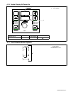
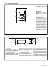
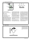
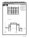
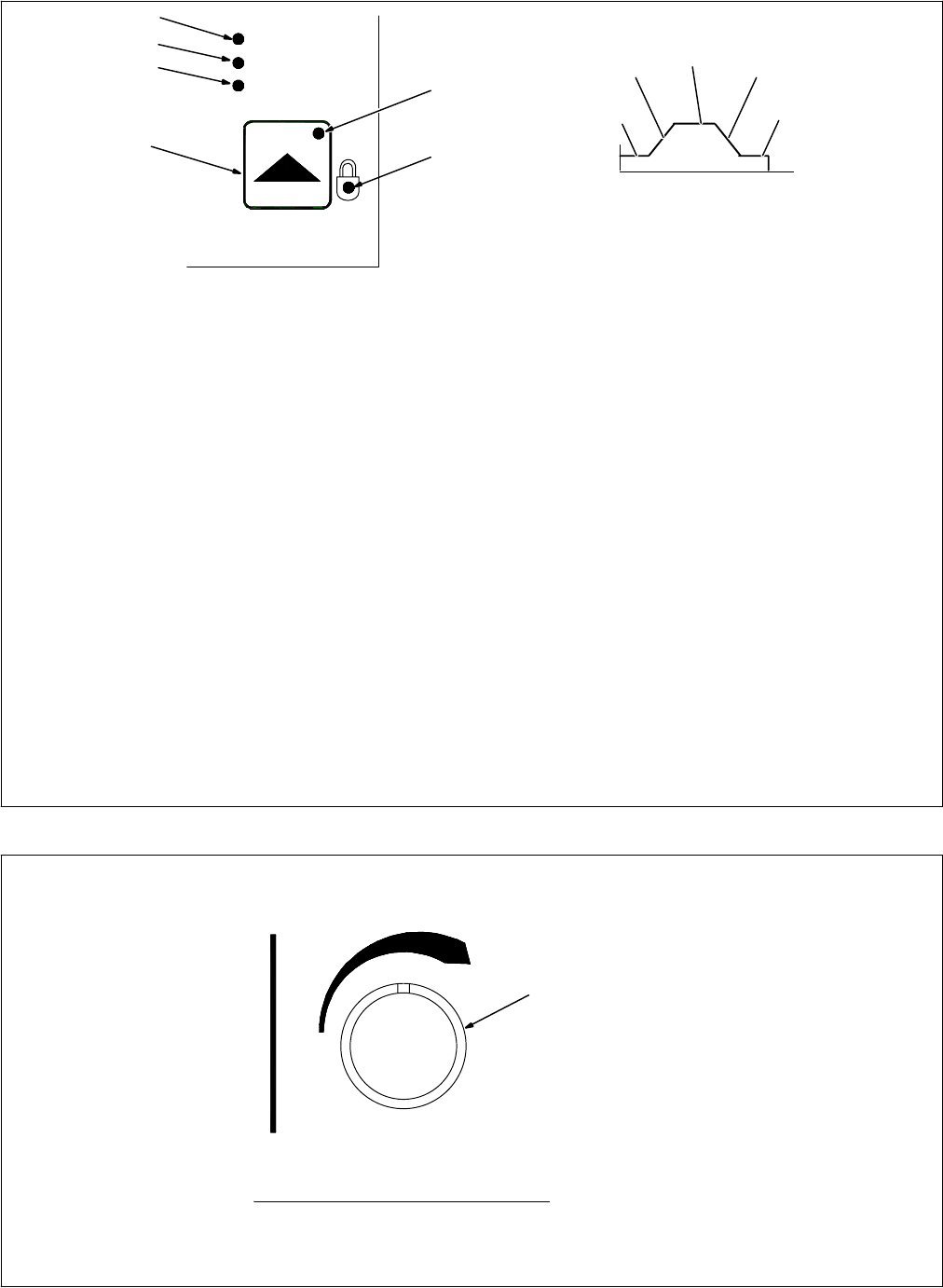
5-7. Feeder Set Up Push Button
1 Feeder Set Up Push Button
2 Feeder Set Up Push Button LED
Press button to choose sequence, trigger
control, or trigger hold.
3 Sequence LED
4 Trigger Control LED
5 Trigger Hold LED
6 Lock LED (Access Allowed Only By
Using An Optional PDA With File
Management Software)
• When the Feeder Set Up button is pressed
while in standby, the Feeder Set Up push
button LED illuminates and the top display
will be active. Use the Adjust control to
select preflow (PRE), start (STRT), crater
(CRTR), or postflow (POST) parameters.
• Press the lower display push button to allow
the bottom display to become active. The
time LED will automatically begin flashing
and the unit will be in the time mode. Initially,
all sequences will appear as off. Use the
Adjust control display time and enable the
time sequence. Setting a time automatically
enables a sequence. To turn off a sequence,
change time setting to OFF.
• If the sequence has a voltage or arc adjust
setting, pressing the lower display push
button a second time will cause either volts
or arc adjust to appear on the display. Use
the Adjust control to set either parameter.
• If the sequence has a wire feed setting,
pressing the lower display push button a
third time will cause wfs to appear on the
display. Use the Adjust control to set wire
speed parameter.
• Press the lower display push button a fourth
time will cycle the display back to time.
• Press the Feeder Set Up button a second
time to go to Trigger Control mode and allow
the top display to become active. Use the
Adjust control to cycle through trigger
control methods as follows: dual schedule,
trigger hold, trigger dual schedule, program
select, 4T (see Section 5-1). The lower
display will show the current state of each
trigger control method as being either on or
off. Not all trigger control methods are
compatible with each other, and turning on
certain functions will cause other trigger
functions to turn off.
• Press the lower display push button to allow
the bottom display to become active. Use
the Adjust control to turn selected trigger
control methods on or off. If trigger hold is
set to on, the trigger hold LED will illuminate.
Note: if 4T is set to on, trigger hold will
automatically be set to on since this
parameter is necessary for the 4T function.
• Press the Feeder Set Up button a third time
to cycle back to standby mode.
1
6
3
4
Trigger Control
Feeder Set Up
Trigger Hold
Sequence
5
Welding Sequence Diagram
Preflow
Time
Start
Time
Weld
Time
Crater
Time
Postflow
Time
2
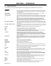
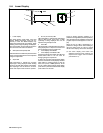
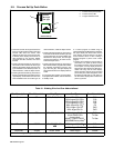
5-8. Adjust Control
Adjust
1
1 Adjust Control
The Adjust control is used to
change various sequence parame-
ters, and to select various se-
quences. Refer to the section for
the function in question for informa-
tion related to using the Adjust con-
trol.