


OM-480 Page 14
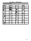
SECTION 5 − INSTALLATION
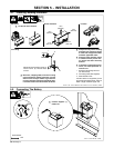
5-1. Installing Welding Generator
install1 11/02 − Ref. ST-800 652 / Ref. ST-800 477-A / ST-158 936-A / S-0854
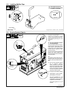
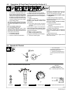
Electrically bond generator frame to
vehicle frame by metal-to-metal
contact.
GND/PE
1
2
Y Always securely fasten welding
generator onto transport vehicle
or trailer and comply with all DOT
and other applicable codes.
Y Always ground generator frame
to vehicle frame to prevent elec-
tric shock and static electricity
hazards.
Y If unit does not have GFCI recep-
tacles, use GFCI-protected ex-
tension cord.
1 Equipment Grounding Terminal
(On Front Panel)
2 Grounding Cable (Not Supplied)
3 Metal Vehicle Frame
Connect cable from equipment ground
terminal to metal vehicle frame. Use #10
AWG or larger insulated copper wire.
3
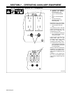
18 in
(460 mm)
18 in
(460 mm)
18 in
(460 mm)
18 in
(460 mm)
18 in
(460 mm)
OR
Movement Airflow Clearance Location
Grounding
OR
Y Do Not Lift Unit From End
Y Bed liners, shipping skids, and some running
gears insulate the welding generator from the
vehicle frame. Always connect a ground wire
from the generator equipment grounding termi-
nal to bare metal on the vehicle frame as shown.
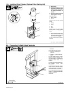
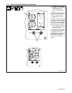
5-2. Connecting The Battery
156 011-A / Ref. 206 029 / S-0756
1/2 in
+
−
Y Connect Negative (−)
Cable Last.
Tools Needed: