


OM-480 Page 30
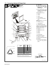
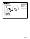
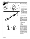
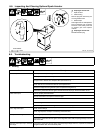
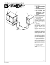
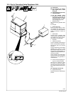
8-8. Inspecting And Cleaning Optional Spark Arrestor
800 523 / Ref. 206 029
Y Stop engine and let cool.
1 Spark Arrestor
2 Cleanout Plug
Remove plug and remove any dirt
covering cleanout hole.
3 Exhaust Pipe
Start engine and run at idle speed to
blow out cleanout hole. If nothing
blows out of hole, briefly cover end
of exhaust pipe with fireproof
material.
Y Stop engine and let cool.
Reinstall cleanout plug.
3
2
1
3/8 in
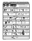
Tools Needed:
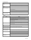
8-9. Troubleshooting
A. Welding
Trouble Remedy
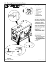
No weld output. Check position of Ampere Range switch.
Check position of optional Polarity switch.
Place A/V control switch in Panel position, or place switch in Remote position and connect Remote Am-
perage control to Remote A/V receptacle RC3 (see Section 6-3).
Check and secure connections to Remote A/V receptacle RC3.
Disconnect equipment from generator power receptacles during start-up.
Have Factory Authorized Service Agent check brushes and slip rings, and field excitation circuit.
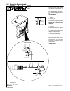
Erratic weld output. Use dry, properly stored electrode.
Be sure connection to work piece is clean and tight.
Remove excessive coils from weld cables.
Check and tighten connections both inside and outside unit.
Have Factory Authorized Service Agent check brushes and slip rings, and field excitation circuit.
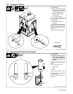
Low or high weld output. Check control settings.
Check engine speed, and adjust if necessary (see Section 8-5).
Low open-circuit voltage.
Check engine speed, and adjust if necessary (see Section 8-5).
Have Factory Authorized Service Agent check integrated rectifier SR2, Amperage/Voltage control R1,
and resistor R2.
Maximum weld output only in each am-
pere range.
Have Factory Authorized Service Agent check Amperage/Voltage control R1, capacitor C8, diode D8,
integrated rectifier SR4, and control relay CR2.