


OM-480 Page 19
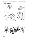
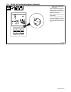
6-2. Description Of Front Panel Controls (See Section 6-1)
.
This unit has a max OCV control circuit
that resets the Amperage/Voltage Con-
trol to maximum when the arc breaks.
When an arc is struck, weld output control
returns to the front panel or remote con-
trol setting. The Amperage/voltage Con-
trol adjusts amperage only when welding
and does not adjust open-circuit voltage.
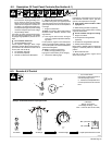
1 Ampere Range Switch
Use switch to select weld amperage range.
For most welding applications, use lowest
amperage range possible to prevent arc out-
ages.
Y Do not switch under load.
2 Amperage/Voltage Control
Control adjusts amperage within range
selected by Ampere Range switch. Weld out-
put would be 148 A DC with controls set as
shown (50% of 95 to 200 A).
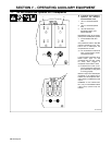
3 DC Voltmeter (Optional)
4 DC Ammeter (Optional)
5 Remote A/V Switch And Receptacle
(See Section 6-3)
6 Magnetic Shutdown Switch (Optional)
Use switch during start-up to bypass optional
engine shutdown system. System stops en-
gine if oil pressure is too low or oil temperature
is too high.
7 Engine Control Switch
To Start: turn switch to Start while pressing
Shutdown switch. Release switches when
engine starts.
. If the engine does not start, let engine
come to a complete stop before attempt-
ing restart.
In Run position, engine runs at weld/power
speed. In Run/Idle position (optional), engine
runs at idle speed at no load and weld/power
speed with load applied.
To Stop: turn switch to Off position.
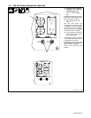
8 Battery Charging Warning Light
Light goes on when battery is not charging.
9 Oil Pressure Warning Light
Light goes on if oil pressure is too low. If unit
has automatic shutdown option, light also
goes on if oil temperature is too high.
Y Stop engine and fix trouble if either
light goes on.
10 Ether Starting Aid Switch (Optional)
Push switch up and release while cranking
engine to release ether.
Y Do not use Ether if engine is running.
11 Engine Hour Meter
12 Oil Temperature Gauge/Switch
(Optional)
13 Oil Pressure Gauge/Switch (Optional)
14 Polarity Switch (Optional)
Place switch in Straight position for electrode
negative, or Reverse position for electrode
positive.
15 Manual Shutoff Lever
Use lever to stop engine if engine control
switch does not work.
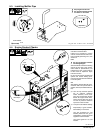
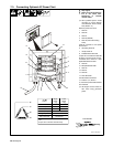
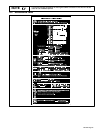
6-3. Remote A/V Control
1 A/V Control Switch
Use switch to select front panel or
remote amperage control.
2 Remote A/V Receptacle RC3
Connect optional remote control to
RC3.
S-0774
1
Min (70 A DC)
Max (148 A DC)
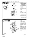
Example: Combination Remote Amperage Control
In Example:
Range = 95 to 200 A
Percentage Of Range = 50%
Max = 148 A DC (50% of 95 to 200)
Adjust Optional Remote ControlSet Switch Set Range Set Percentage
2