


OM-229 979 Page 29
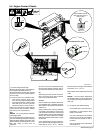
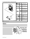
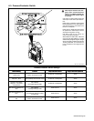
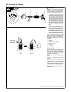
6-3. Process/Contactor Switch
1 Process/Contactor Switch
! Weld output terminals are ener-
gized when Process/Contactor
switch is in a Weld Terminals Al-
ways On position and the engine
is running.
Use switch to select weld process and
weld output on/off control (see table be-
low).
Place switch in Remote On/Off Switch
Required positions to turn weld output on
and off with a device connected to the
Remote 14 receptacle.
Place switch in Weld Terminals Always
On positions for weld output to be on
whenever the engine is running.
Use Stick mode for air carbon arc
(CAC-A) cutting and gouging.
When switch is in Stick mode, select one
of four arc drive (dig) settings to provide
additional amperage during low voltage
(short arc length) conditions and prevent
“sticking” electrodes. Turn control from A
to D to increase arc drive (dig) from min
to max.
1
229 747-B / 804 630-A
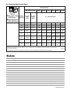
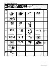
Process/Contactor Switch Settings
Switch Setting
Process
Output On/Off Control
Engine Auto Idle (Optional)
Switch Setting Process Output On/Off Control Engine Auto Idle (Optional)
Remote On/Off Switch Re-
quired −TIG
GTAW With HF Unit, Pulsing
Device, Or Remote Control
At Remote 14 Receptacle Active
Remote On/Off Switch
Required − Stick
Stick (SMAW) With Remote On/Off At Remote 14 Receptacle Active
Remote On/Off Switch
Required − CV Feeder
Using Remote
MIG (GMAW)
w/Constant Speed Feeder
At Remote 14 Receptacle Active
Weld Terminals Always On −
Wire
MIG (GMAW)
w/Voltage Sensing Feeder
Electrode Hot Active
Weld Terminals Always On −
Stick
Stick (SMAW),
Air Carbon Arc (CAC-A) Cutting
And Gouging
Electrode Hot Active
Weld Terminals Always On −
TIG
GTAW With HF Unit, Pulsing
Device, Or Remote Control
Electrode Hot Active