


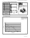
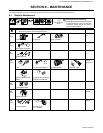
. Complete Parts List available at www.MillerWelds.com
OM-4417 Page 21
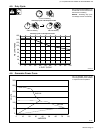
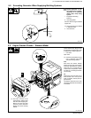
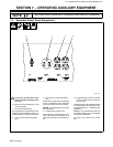
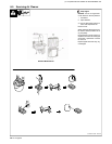
6-2. Description Of Controls (Standard Models) (See Section 6-1)
1 Engine Switch
Use switch to control ignition circuit. Turn
switch to On position when starting engine.
Turn switch to Off position to stop engine. En-
gine cannot be started with switch in the Off
position.
Engine stops if oil level is too low. Engine can-
not be restarted until sufficient oil is added.
2 Low Oil Pressure Light
Light goes on and engine stops if engine oil
level is too low.
Engine cannot be restarted until sufficient oil
is added.
! Stop engine and add oil if light goes on
(see Section 5-4).
3 Starter Handle
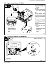
4 Choke Control
Use control to change engine air/fuel mix.
Move control to far right if starting a cold en-
gine. Move control to far left if starting a warm
engine.
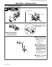
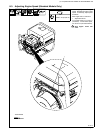
To Start:
D Open fuel valve (see Section 5-4).
D Turn Engine switch to On.
D Set choke.
D Pull starter handle. Open choke as en-
gine warms.
! If the engine does not start, let engine
come to a complete stop before at-
tempting restart.
To Stop:
D Turn Engine switch to Off.
. Always close fuel valve after stopping
unit. Moving unit with fuel valve open may
cause carburetor flooding and make
starting difficult.
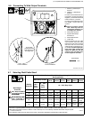
5 Welding Range Table
Use table to determine correct weld amper-
age based on electrode size, type, and mate-
rial thickness.
6 Weld Output Control
. Set control at maximum for full generator
power output at AC receptacles
Use control to select weld amperage. Control
may be adjusted while welding.
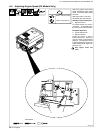
To Set Weld Output Control: Use table to
determine correct size electrode for weld am-
perage. Select electrode type and set control
to corresponding amperage range on name-
plate. Adjust control to obtain desired weld
performance.
EXAMPLE:
Electrode Diameter: 1/8
Electrode Type: E-6013
Current Control Setting: 90 − 120 A
Notes
Work like a Pro!
Pros weld and cut
safely. Read the
safety rules at
the beginning
of this manual.