


. Complete Parts List available at www.MillerWelds.com
OM-4417 Page 23
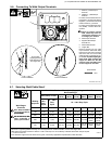
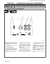
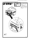
6-4. Description Of Controls (DX Models) (See Section 6-3)
1 Engine Switch
Use switch to control ignition circuit. Turn
switch to Start position for electric start. Turn
switch to On position to start engine using
starter handle (recoil). Turn switch to Off posi-
tion to stop engine.
2 Low Oil Level Light
Light goes on and engine stops if engine oil
level is too low.
Engine cannot be restarted until sufficient oil
is added.
! Stop engine and add oil if light goes on
(see Section 5-4).
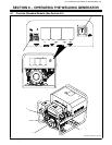
3 Starter Handle
Use starter handle to start unit if electric start
does not work.
4 Choke Control
Use control to change engine air/fuel mix.
Move control to far right if starting a cold en-
gine. Move control to far left if starting a warm
engine.
The engine starts at weld/power speed and
runs at weld/power speed under weld or gen-
erator power load. The engine returns to idle
speed 12 seconds after start-up or after weld
or generator power load is removed.
To Start:
D Open fuel valve (see Section 5-4).
D Set choke.
D Electric-Start: Turn Engine switch to
Start position.
Recoil: Turn Engine switch to On posi-
tion. Pull starter handle until engine
starts.
D Open choke as engine warms.
! If the engine does not start, let engine
come to a complete stop before at-
tempting restart.
To Stop:
D Turn Engine switch to Off.
. Always close fuel valve after stopping
unit. Moving unit with fuel valve open may
cause carburetor flooding and make
starting difficult.
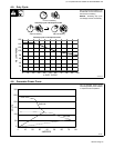
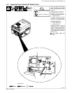
5 Welding Range Table
Use table to determine correct weld amper-
age based on electrode size, type, and mate-
rial thickness.
6 Run / Idle Switch
Use switch to select whether the engine stays
at run speed continuously or whether the auto
idle feature is enabled so engine speed re-
turns to idle speed after start−up or after weld
or generator load is removed.
7 Weld Output Control
. Set control at maximum for full generator
power output at AC receptacles.
Use control to select weld amperage. Control
may be adjusted while welding.
To Set Weld Output Control: Use table to
determine correct size electrode for weld am-
perage. Select electrode type and set control
to corresponding amperage range on name-
plate. Adjust control to obtain desired weld
performance.
EXAMPLE:
Electrode Diameter: 1/8
Electrode Type: E-6013
Current Control Setting: 90 − 120 A
8 Hourmeter
Use hourmeter to help schedule routine main-
tenance.
Notes
Work like a Pro!
Pros weld and cut
safely. Read the
safety rules at
the beginning
of this manual.