


OM-184 227 Page 8
sb7.1* 3/93 - Ref. S-0004-A / Ref. S-0750 / Ref. ST-801 826-C
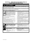
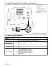
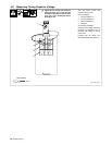
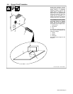
3-3. Remote 14 Receptacle RC14 Information and Connections
1 Front Panel
2 Plug
3 Threaded Collar
4 Keyway
5 Remote 14 Receptacle RC14
(See Section 3-4)
To connect to receptacle, align key-
way, insert plug, and tighten
threaded collar.
2
3
AJ
B
K
I
C
L
NH
D
M
G
E
F
4
5
1
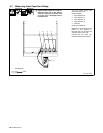
3-4. Remote 14 Socket Information
Socket Socket Information
Remote Contactor
A
+24 volts dc.
R
emote
C
ontactor
B
Contact closure to A completes 24 volts dc contactor control circuit.
C
Command reference; +10 volts dc.
Remote Output Control
D
Control circuit common.
R
emote
O
utput
C
ontro
l
E
Input command signal (potentiometer wiper or 0 to +10 volts dc).
G
Not used.
Power Source Limit F, J
Absence of internal contact closure between F and J signals power source failure to remote
control device.
H
Coil loss compensation value.
H
I
p
Actual frequency output signal (1 volt/10 kHz).
Remote Metering
I
L
Average power output signal (1 volt/5 kW).
R
emote
M
eter
i
ng
M
Voltage output signal RMS (1 volt/100 volts).
N
Current output signal RMS (1 volt/100 amperes).
Ch i
K
Chassis common.