


OM-184 227 Page 15
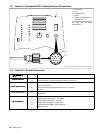
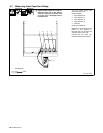
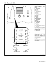
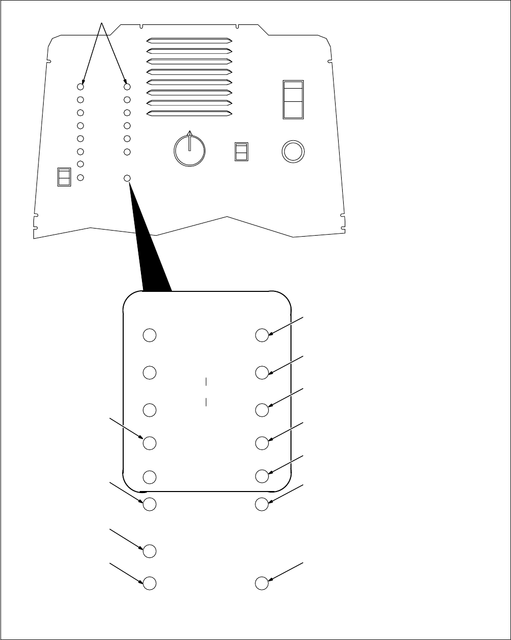
5-8. Diagnostic LED’s
Ref. ST-801 826-B
1 Diagnostic LED’s
Use diagnostic LED’s to determine
operating condition of power
source.
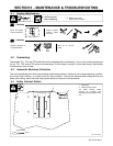
2 Current Source
Limit: 110 A
Fault: 115 A
3 Over Frequency
Limit: 50 kHz
Fault: 55 kHz
4 Under Frequency
Limit: 10 kHz
Fault: 5 kHz
5 Current
Reactive Limit: 700 A
6 Tank Voltage
Limit: 670 V
Fault: 1100 V Peak
7 Line Voltage
Fault: ±20 %
8 Contactor
Lights when contactor is energized.
9 Over Temp
Lights when contactor is energized
and over temperature condition is
present. Also indicates top cover is
removed from unit.
10 Tank Current
Fault Value Preset At Factory
11 Ground Fault
Lights when the ground fault
circuitry detects a short in the
output circuit between the
workpiece and power source, or
when test switch is pressed to test
ground fault circuitry.
12 Load
Lights when no load or insufficient
load is present to couple with the
coil or blanket.
1
LIMITFAULT
CURRENT
SOURCE
OVER
FREQUENCY
UNDER
CURRENT
TANK VOLTAGE
LINE VOLTAGE
CONTACTOR
OVERTEMP
2
3
4
5
6
8
7
12
10
11
GROUND FAULT
LOAD
9