


OM-184 227 Page 16
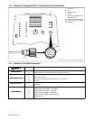
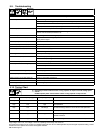
5-9. Troubleshooting
Trouble Remedy
No heat output. Replace building line fuse or reset circuit breaker.
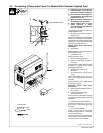
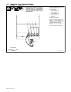
Secure head/coil connecting plate to power source connecting block (see Section 3-2).
Check and replace Power switch if necessary.
Connect power source to proper input voltage or check for low line voltage.
No heat output; fan motor continues to run. Safety interlock switch open. Reinstall wrapper (see Section 5-4).
Thermostat(s) TP1, TP2, and/or TP3 open (overheating). Allow fan to run; the thermostat(s) will close
when the unit has cooled (see Section 5-2).
Low heat output. Check tuning of induction heating output system.
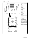
Current Source Fault LED (red) on. Turn power off and back on again to power source one time. If fault does not clear, contact authorized
Factory Service Agent.
Over Frequency Fault LED (red) on. Check for shorted coil or blanket.
Under Frequency Fault LED (red) on. Check for open circuit coil or blanket.
Current Fault LED (red) on. Check for shorted turn(s) in coil or blanket.
Tank Voltage Fault LED (red) on. Check for unloaded (empty) coil.
Check for arcing between turns.
Line Voltage Fault LED (red) on. Check input line voltage.
Ground Fault LED (red) on. Check for output path to ground.
Check for human path to ground.
Load Fault LED (red) on. Check for loose coupling between coil or blanket and workpiece or pipe.
Over Temperature Fault LED (yellow) on. Check door switch.
Check for fan operation.
Clean unit.
Current Source Limit LED (yellow) on. Check coupling between coil and load.
Over Frequency Limit LED (yellow) on. Check for correct tank capacitance.
Check for shorted turns.
Under Frequency Limit LED (yellow) on. Check for correct tank capacitance.
Current Limit LED (yellow) on. Check tank capacitance.
Tank Voltage LED (yellow) on. Check tuning of system (see Section 5-10).
5-10. Tuning Chart
Y Energizing contactor without at least 1 tuning capacitor in output circuit will damage power
source.
DO NOT operate power source without at least 1 tuning capacitor in output circuit.
Voltage* Current (Amperage)* Frequency (KHz) Corrective Action
High Low Low Lower inductance or decrease matching transformer turns ratio
High Low High Add capacitance
High Low Mid-Range Decrease matching transformer turns ratio and add capacitance
Low High Low Lower capacitance
Low High High Increase matching transformer turns ratio, or lower capacitance and
increase inductance
Low High Mid-Range Increase matching transformer turns ratio and lower capacitance
*High voltage > 650 V rms; Low voltage < 450 V rms; Operating current range: 0 to 750 A rms
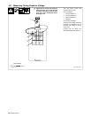
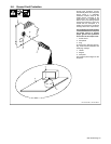
The power source is factory set for 4.5 mfd, but is capable of being set for 6 mfd. If a certain application requires the higher capacitance setting, remove
insulator from front capacitor and connect with supplied hardware.