


OM-185 648 Page 18
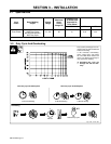
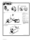
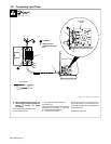
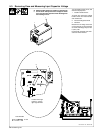
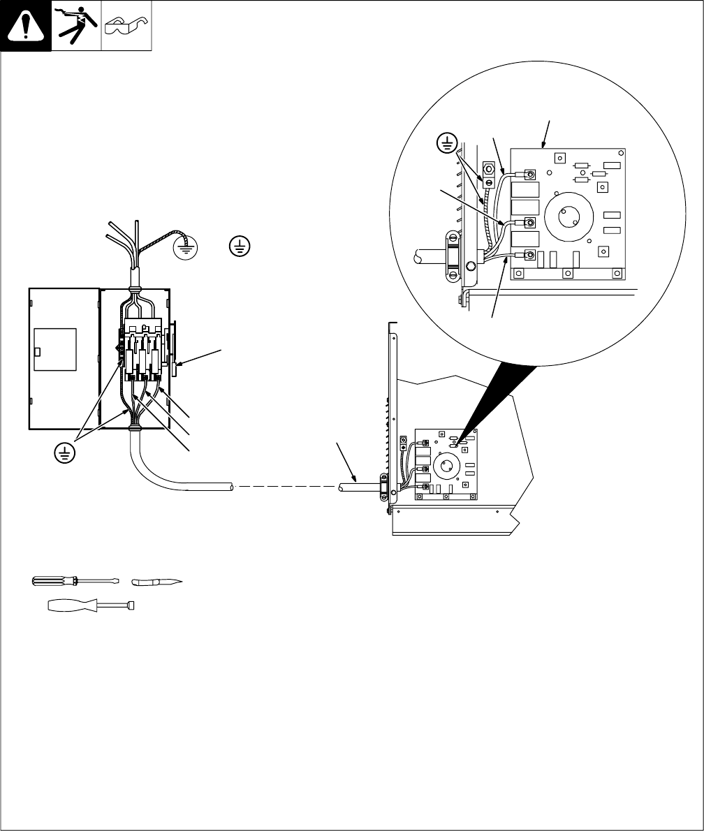
3-9. Connecting Input Power
ssb2.4* 1/94 – ST-801 718 / ST-801 946
Tools Needed:
5/16 in
Input Filter
Board
L1
=GND/PE
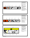
Y Always connect
grounding conductor
first.
Y Turn Off welding power source, and
check voltage on input capacitors ac-
cording to Section 5-3 before
proceeding.
Check input voltage available at site.
Remove left side panel.
1 Input And Grounding Conductors
See Section 3-8.
Install ring terminals of proper size onto input
conductors for connection to input filter
board terminals (see illustration).
2 Line Disconnect Device
Select type and size of overcurrent protec-
tion using Section 3-8. Connect input and
grounding conductors to a deenergized line
disconnect device.
Reinstall left side panel.
L1
2
L2
L3
1
L2
L3