


OM-185 648 Page 22
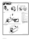
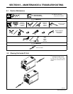
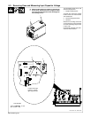
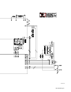
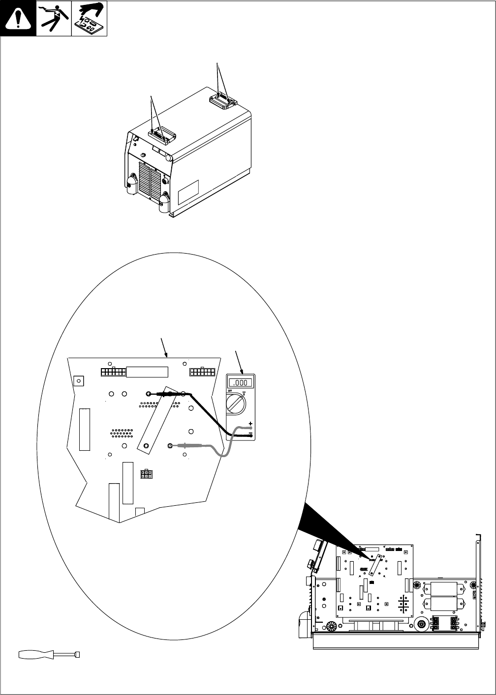
5-3. Removing Case and Measuring Input Capacitor Voltage
Turn Off welding power source, and
disconnect input power.
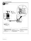
1 Outside Handle Screws
To loosen top, remove two outside
handle screws from both handles
and all side bolts.
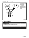
2 Interconnecting Board PC2
3 Voltmeter
Measure the dc voltage across the
screw terminals on RC3 and RC5
as shown until voltage drops to near
0 (zero) volts.
Proceed with job inside unit. Rein-
stall cover when finished.
Tools Needed:
5/16 in
Ref. ST-801 718 / ST-801 536
Y Significant DC voltage can remain on capacitors af-
ter unit is Off. Always check the voltage as shown
to be sure the input capacitors have discharged be-
fore working on unit.
2
3
+ lead to lower right
terminal, – lead to
upper right terminal
1
1