


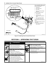


OM-1572 Page 7
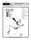
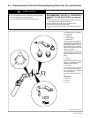
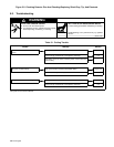
5-2. Checking Detector Pins And Checking/Replacing Shield Cup, Tip, And Electrode
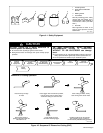
CAUTION
OVERTIGHTENING will strip threads.
• Do not overtighten electrode, tip, and shield cup during assembly.
• Do not cross-thread parts causing stripping.
• Use care during torch assembly and parts replacement.
TIP AND ELECTRODE WEAR BEYOND
RECOMMENDED VALUES or OPERATION
WITHOUT TIP OR ELECTRODE can damage
torch.
• Inspect shield cup, tip, and electrode before cutting or whenever
cutting speed has been significantly reduced.
• Do not operate torch without a tip or electrode in place.
• Be sure to use genuine replacement parts.
• A good practice is to replace both the tip and electrode at the same
time.
Ref. ST-800 225 / Ref. S-0093
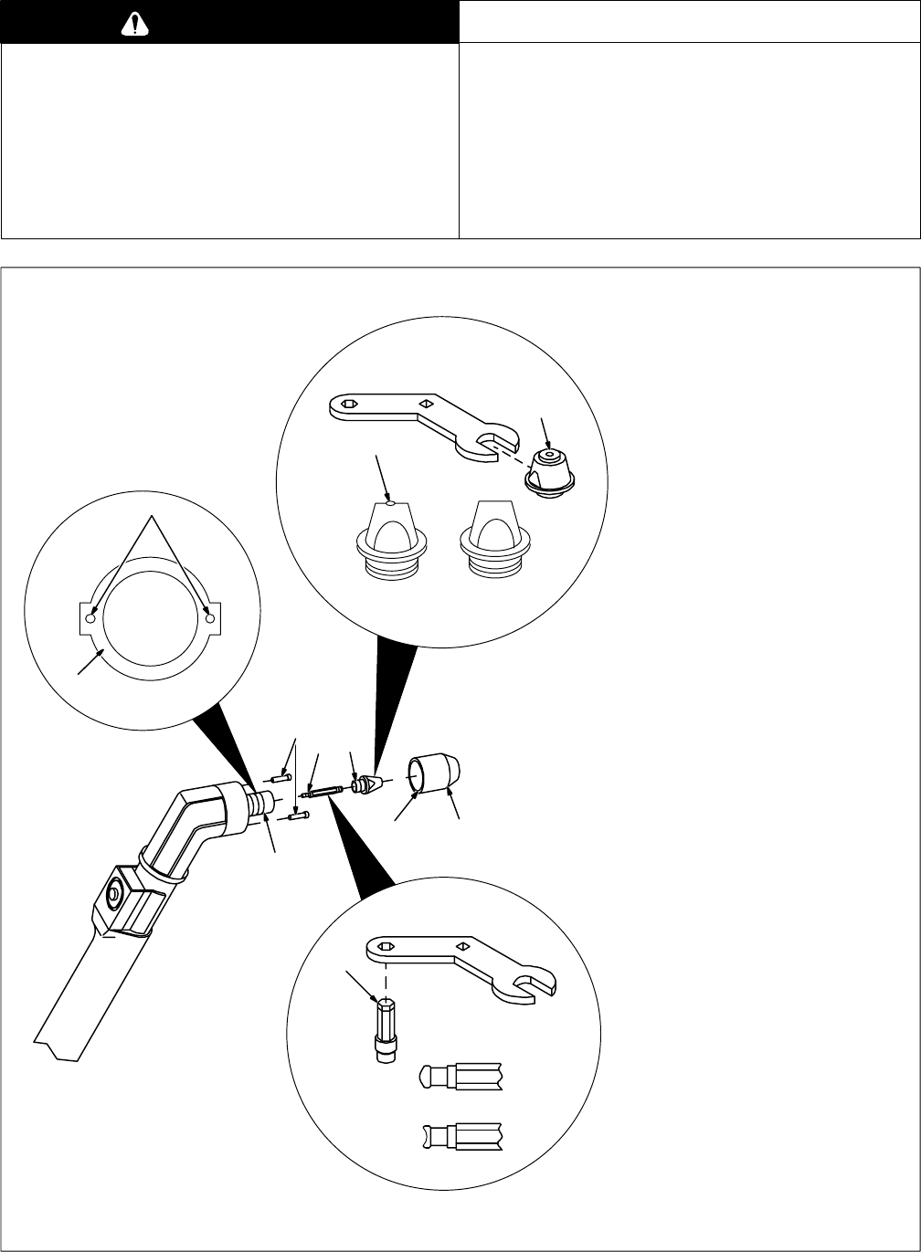
Turn Off power source, and discon-
nect input power.
1 Shield Cup
2 Contact Surface
3 Detector Pins
Unscrew shield cup, and wipe con-
tact surfaces with a soft cloth. Con-
tact surfaces must be clean so
spring-loaded detector pins de-
press when shield cup is installed.
Check shield cup for cracks, and
replace if necessary.
Check detector pins to make sure
they move freely. If necessary, use
electrical contact cleaner to loosen
them.
4Tip
5 Opening
Remove tip using supplied wrench.
Check tip, and replace if opening is
deformed or 50% oversize.
6 Electrode
Check electrode. If more than 0.039
in (1 mm) of the end is eroded, re-
move electrode using supplied
wrench, and replace.
Carefully reassemble in reverse or-
der.
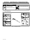
Thread Sizes:
A M8 x .75
B M3 x .5
C M12 x 1
New
Worn
New Worn
4
5
6
2
3
21
C
B
3
A