


a
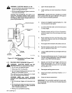
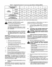
WARNING:
ELECTRIC
SHOCK
can
kill.
Do
not
connect
an
input
(white
or
black)
con
ductor
to
the
ground
term
mal.
Do
not
connect
the
ground
(green)
conductor
to
an
input
line
terminal.
Incorrect
input
connections
can
result
in
an
electrically
energized
welding
power
source
chassis.
The
ground
terminal
is
connected
to
the
welding
power
source
chassis
and
is
for
grounding
purposes
only.
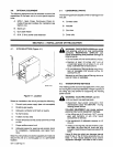
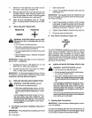
Wall
Receptacle
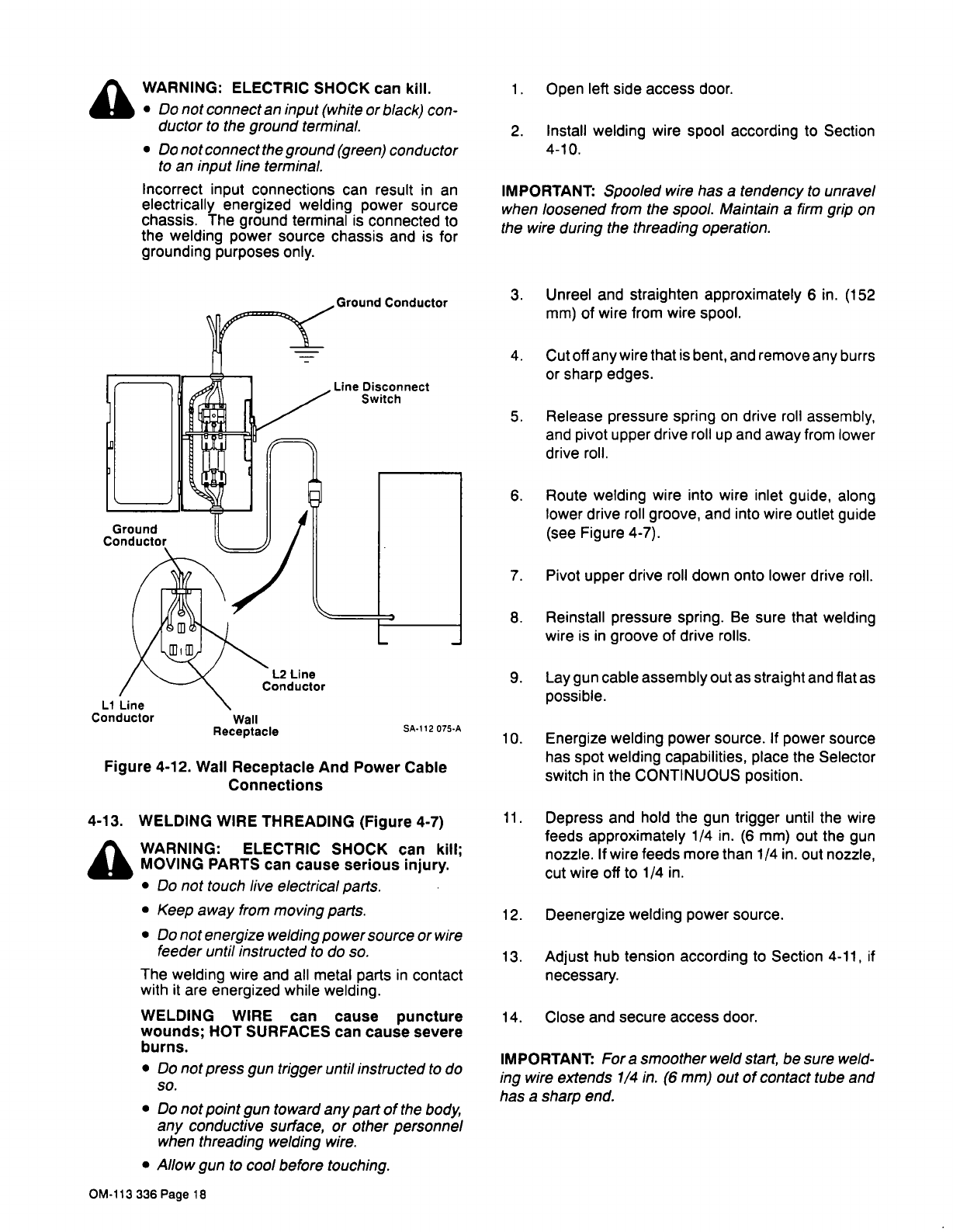
Figure
4-12.
Wall
Receptacle
And
Power
Cable
Connections
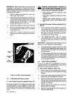
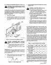
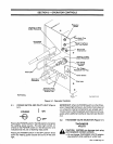
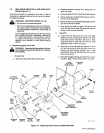
4-13.
WELDING
WIRE
THREADING
(Figure
4-7)
a
WARNING:
ELECTRIC
SHOCK
can
kill;
MOVING
PARTS
can
cause
serious
injury.
Do
not
touch
live
electrical
parts.
Keep
away
from
moving
parts.
Do
not
energize
welding
power
source
or
wire
feeder
until
instructed
to
do
so.
The
welding
wire
and
all
metal
parts
in
contact
with
it
are
energized
while
welding.
WELDING
WIRE
can
cause
puncture
wounds;
HOT
SURFACES
can
cause
severe
burns.
Do
not
press
gun
trigger
until
instructed
to
do
so.
Do
not
point
gun
toward
any
part
of
the
body,
any
conductive
surface,
or
other
personnel
when
threading
welding
wire.
Allow
gun
to
cool
before
touching.
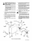
1.
Open
left
side
access
door.
2.
Install
welding
wire
spool
according
to
Section
4-10.
IMPORTANT:
Spooled
wire
has
a
tendency
to
unravel
when
loosened
from
the
spool.
Maintain
a
firm
grip
on
the
wire
during
the
threading
operation.
3.
Unreel
and
straighten
approximately
6
in.
(152
mm)
of
wire
from
wire
spool.
4.
Cutoff
any
wire
that
is
bent,
and
remove
any
burrs
or
sharp edges.
5.
Release
pressure
spring
on
drive
roll
assembly,
and
pivot
upper
drive
roll
up
and
away
from
lower
drive
roll.
6.
Route
welding
wire
into
wire
inlet
guide,
along
lower
drive
roll
groove,
and
into
wire
outlet
guide
(see
Figure
4-7).
7.
Pivot
upper
drive
roll
down
onto
lower
drive
roll.
8.
Reinstall
pressure
spring.
Be
sure
that
welding
wire
is
in
groove
of
drive
rolls.
9.
Lay
gun
cable
assembly
out
as
straight
and
flat
as
possible.
10.
Energize
welding
power
source.
If
power
source
has
spot
welding
capabilities,
place
the
Selector
switch
in
the
CONTINUOUS
position.
11.
Depress
and
hold
the
gun
trigger
until
the
wire
feeds
approximately
1/4
in.
(6
mm)
out
the
gun
nozzle.
If
wire
feeds
more
than
1/4
in.
out
nozzle,
cut
wire
off
to
1/4
in.
12.
Deenergize
welding
power
source.
13.
Adjust
hub
tension
according
to
Section
4-11,
if
necessary.
14.
Close
and
secure
access
door.
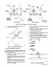
IMPORTANT:
For
a
smoother
weld
start,
be
sure
weld
ing
wire
extends
1/4
in.
(6
mm)
out
of
contact
tube
and
has
a
sharp
end.
Ground
Conductor
Line
Disconnect
Switch
Li
Line
Conductor
L2
Line
Conductor
SA-112
075-A
OM-113
336
Page
18