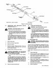
b.
Place
Selector
Switch
on
optional
SPW-1
panel
in
CONTINUOUS
position,
and
set
welding
volt
age
and
wire
feed
speed
parameters
according
to
Steps
8
thru
15
in
Section
6-1.
(Set
voltage
and
wire
feed
speed
for
metal
thickness
of
sam
ple
metal.)
IMPORTANT:
Use
in
CONTINUOUS
position
serves
as
coarse
adjustment
of
unit
for
SPOTmode
operation.
Arc
length
and
weld
puddle
can
not
be
observed
with
spot
welding
nozzle
installed
on
gun.
Several
pieces
of
double
thickness
metal
maybe
required
to
coarse
adjust
unit.
c.
After
voltage
and
wire
feed
speed
parameters
have
been
set,
deenergize
welding
power
source,
remove
continuous
welding
nozzle
from
gun,
and
replace
nozzle
with
appropriate
spot
welding
nozzle.
d.
Obtain
sample
pieces
of
metal
the
same
type
and
thickness
of
final
workpiece.
e.
Place
welding
power
source
in
SPOT
mode,
and
rotate
SPOT
TIME/PULSE
ON
TIME
and
BURNBACK
TIME
controls
to
desired
settings.
IMPORTANT:
The
correct
burnback
time
allows
the
wire
to
burn
back
just
free
of
the
weld
puddle.
If
the
weld
ing
wire
freezes
to
the
workpiece
at
the
end
of
the
weld
cycle,
increase
burnback
time.
If
the
welding
wire
burns
back
into
the
contact
tube,
decrease
burnback
time.
If
the wire
burns
back
into
the
contact
tube,
it
may
be
nec
essary
to
replace
the
contact
tube
in
the
gun.
(See
gun
Owners
Manual
for
contact
tube
replacement
proce
dure.)
f.
Make
several
practice
spot
welds
to
determine
if
weld
parameters
are
set
correctly.
(Refer
to
Table
6-2
to
check
sample
weld.)
To
spot
weld,
place
gun
nozzle
directly
on
work-
piece,
hold
gun
motionless,
and
depress
gun
trigger.
When
trigger
is
depressed,
welding
wire
and
shielding
gas
will
feed
for
the
length
of
time
set
on
the
SPOT
TIME/PULSE
ON
TIME
Control.
IMPORTANT:
The
welding
wire
is
not
energized
until
the
gun
trigger
is
pressed;
therefore,
the
operator
can
accurately
position
gun
on
weld
joint
before
lowering
helmet
and
pressing
gun
trigger.
IMPORTANT:
The
gun
trigger
must
be
held
closed
until
the
SPOT
TIME/PULSE
ON
TIME
control
has
timed
Out,
completing
the
spot
weld
cycle.
If
the
trigger
is
released
before
the
cycle
is
complete,
the
cycle
stops,
and
the
unit
resets
for
another
weld
cycle.
6.
After
all
weld
parameters
have
been
set,
prepare
weld
joint
(see
Sections
9
and
10),
and
weld
final
workpiece.
6-3.
SHUTTING
DOWN
1.
Stop
welding.
2.
Shut
down
welding
power
source.
3.
Turn
off
shielding
gas
at
the
source.
a
WARNING:
HIGH
CONCENTRATION
OF
SHIELDING
GAS
can
harm
health
or
kill.
Shut
off
gas
supply
when
not
in
use.
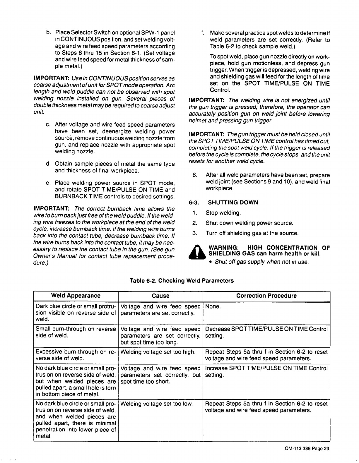
Table
6-2.
Checking
Weld
Parameters
Weld
Appearance
Cause
Correction
Procedure
Dark
blue
circle
or
small
protru-
sion
visible
on
reverse
side
of
weld.
Voltage
and
wire
feed
speed
parameters
are
set
correctly.
None.
Small
burn-through
on
reverse
side
of
weld.
Voltage
and
wire
feed
speed
parameters
are
set
correctly,
but
spot
time
too
long.
DecreaseSPOTTIME/PULSEONTIMEControI
setting.
Excessive
burn-through
on
re-
verse
side
of
weld.
Welding
voltage
set
too
high.
Repeat
Steps
5a
thru
f
in
Section
6-2
to
reset
voltage
and
wire
feed
speed
parameters.
No
dark
blue
circle
or
small
pro-
trusion
on
reverse
side
of
weld,
but
when
welded
pieces
are
pulled
apart,
a
small
hole
is
torn
in
bottom
piece
of
metal.
Voltage
and
wire
feed
speed
parameters
set
correctly,
but
spot
time
too
short.
Increase
SPOT
TIME/PULSE
ON
TIME
Control
setting.
No
dark
blue
circle
or
small
pro-
trusion
on
reverse
side
of
weld,
and
when
welded
pieces
are
pulled
apart,
there
is
minimal
penetration
into
lower
piece
of
metal.
Welding
voltage
set
too
low.
Repeat
Steps
5a
thru
f
in
Section
6-2
to
reset
voltage
and
wire
feed
speed
parameters.
OM-113
336
Page
23


