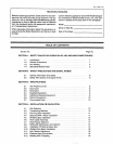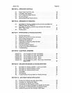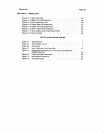
Section
No.
Page
No.
SECTION
11
PARTS
LIST
Figure
11-1.
Main
Assembly
42
Figure
11-2.
Baffle,
Air
w/Components
44
Figure
11-3.
Drive
Assembly,
Wire
46
Figure
11-4.
Panel,
Rear
w/Components
47
Figure
11-5.
Panel,
Front
w/Components
48
Figure
11-6.
SPW
1
Spot
Panel
(Optional)
50
Figure
11-7.
Circuit
Card,
Dual
Timer/Pulser
P050
51
Figure
11-8.
Running
Gear
52
LIST
OF
CHARTS
AND
TABLES
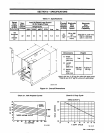
Table
3-1.
Specifications
7
Chart
3-1.
Volt-Ampere
Curves
7
Chart
3-2.
Duty
Cycle
7
Table
4-1.
Input
Conductor
And
Fuse
Size
17
Table
6-1.
Suggested
Parameters
For
Continuous
Gas
Metal
Arc
Welding
(GMAW)
22
Table
6-2.
Checking
Weld
Parameters
23
Table
7-1.
Maintenance
Schedule
24
Table
7-2.
Troubleshooting
29


