


OM-2243 Page 17
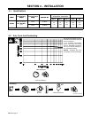
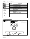
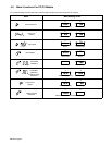
4-8. Weld Output Terminals And Selecting Cable Sizes
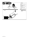
! Turn Off power before
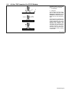
Total Cable (Copper) Length In Weld Circuit Not Exceeding
! T
urn
Off
power
b
e
f
ore
connecting to weld
output terminals.
100 ft (30 m) Or Less
150 ft
(45 m)
200 ft
(60 m)
250 ft
(70 m)
300 ft
(90 m)
350 ft
(105 m)
400 ft
(120 m)
Welding
Amperes
10 − 60%
Duty
Cycle
60 − 100%
Duty Cycle
10 − 100% Duty Cycle
100 4 4 4 3 2 1 1/0 1/0
150 3 3 2 1 1/0 2/0 3/0 3/0
200 3 2 1 1/0 2/0 3/0 4/0 4/0
250 2 1 1/0 2/0 3/0 4/0 2-2/0 2-2/0
300 1 1/0 2/0 3/0 4/0 2-2/0 2-3/0 2-3/0
350 1/0 2/0 3/0 4/0 2-2/0 2-3/0 2-3/0 2-4/0
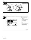
Negative
Positive
Terminal
400 1/0 2/0 3/0 4/0 2-2/0 2-3/0 2-4/0 2-4/0
Terminal
500 2/0 3/0 4/0 2-2/0 2-3/0 2-4/0 3-3/0 3-3/0
600 3/0 4/0 2-2/0 2-3/0 2-4/0 3-3/0 3-4/0 3-4/0
700 4/0 2-2/0 2-3/0 2-4/0 3-3/0 3-4/0 3-4/0 4-4/0
*Weld cable size (AWG) is based on either a 4 volts or less drop or a current density of at least 300 circular mils per ampere. Contact your distributor for
the mm
2
equivalent weld cable sizes. S-0007-E
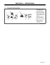
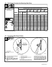
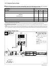
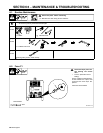
4-9. Connecting Weld Output Cables
803 778-B
! Turn off power before connecting to
weld output terminals.
! Failure to properly connect weld
cables may cause excessive heat
and start a fire, or damage your ma-
chine.
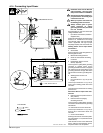
1 Weld Output Terminal
2 Supplied Weld Output Terminal Nut
3 Weld Cable Terminal
4 Copper Bar
Remove supplied nut from weld output ter-
minal. Slide weld cable terminal onto weld
output terminal and secure with nut so that
weld cable terminal is tight against copper
bar. Do not place anything between weld
cable terminal and copper bar. Make
sure that the surfaces of the weld cable
terminal and copper bar are clean.
Tools Needed:
3/4 in (19 mm)
4
2
3
Do not place
anything between
Correct Installation
Incorrect Installation
1
weld cable terminal
and copper bar.