


OM-2243 Page 19
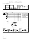
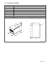
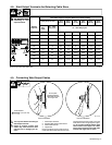
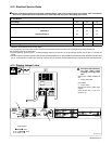
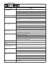
4-12. Electrical Service Guide
Failure to follow these electrical service guide recommendations could create an electric shock or fire hazard. These recommenda-
tions are for a dedicated branch circuit sized for the rated output and duty cycle of the welding power source.
60 Hertz Models
Input Voltage 230 460 575
Input Amperes At Rated Output 58 29 23
Max Recommended Standard Fuse Rating In Amperes
1
Time-Delay
2
70 35 25
Normal Operating 3 90 40 35
Min Input Conductor Size In AWG 4 6 10 10
Max Recommended Input Conductor Length In Feet (Meters) 145 (44) 243 (74) 380 (116)
Min Grounding Conductor Size In AWG 4 8 10 10
Reference: 2005 National Electrical Code (NEC)
1 If a circuit breaker is used in place of a fuse, choose a circuit breaker with time-current curves comparable to the recommended fuse.
2 “Time-Delay” fuses are UL class “RK5” .
3 “Normal Operating” (general purpose − no intentional delay) fuses are UL class “K5” (up to and including 60 amp), and UL class “H” ( 65 amp and
above).
4 Conductor data in this section specifies conductor size (excluding flexible cord or cable) between the panelboard and the equipment per NEC Table
310.16. If a flexible cord or cable is used, minimum conductor size may increase. See NEC Table 400.5(A) for flexible cord and cable requirements.
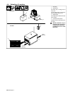
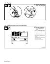
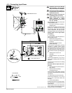
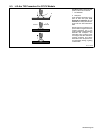
4-13. Placing Jumper Links
Ref. 800 103-A
! Disconnect and lockout/tag-
out input power before
installing or moving jumper
links.
Check input voltage available at
site.
1 Jumper Link Label
Check label.
2 Jumper Links
Move jumper links to match input
voltage.
Close access door, or go on to
Section 4-14.
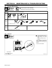
Tools Needed:
3/8 in
3/8 in
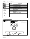
L1(U)
S−174 973−B
GND/ PE
3
Connect
GND/PE
Conductor
First.
I nput
Con t actor
L2(V)
L3(W)
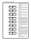
230 VOLTS
460 VOLTS
575 VOLTS
Donot
overtighten
jumperlinknuts.
1
2