


OM-2243 Page 25
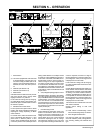
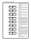
6-3. Voltmeter/Ammeter Help Displays
. All directions are in reference to the front of the unit.
All circuitry referred to is located inside the unit.
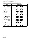
1 Help 0 Display
Indicates a shorted thermistor in the transformer of the
unit. If this display is shown, contact a Factory Autho-
rized Service Agent.
2 Help 2 Display
Indicates a malfunction in the thermal protection circuit-
ry located on the transformer of the unit. If this display
is shown, contact a Factory Authorized Service Agent.
3 Help 3 Display
Indicates the transformer of the unit has overheated.
The unit has shut down to allow the fan to cool it (see
Section 4-2). Operation will continue when the unit has
cooled.
4 Help 4 Display
Indicates a malfunction in the thermal protection circuit-
ry located on the secondary heat sink of the unit. If this
display is shown, contact a Factory Authorized Service
Agent.
5 Help 5 Display
Indicates the secondary heat sink of the unit has over-
heated. The unit has shut down to allow the fan to cool
it (see Section 4-2). Operation will continue when the
unit has cooled.
6 Help 6 Display
This is a two-stage error. The warning stage occurs
when the primary voltage drops more than 12% below
the linked primary voltage setting for more than 30 sec-
onds. The display flashes a HELP 6 message during
idle, but the welder continues to operate normally. Once
the primary voltage returns to less than 10% below the
linked primary voltage setting the flashing error ceases.
The shutdown stage occurs when the primary voltage
drops more than 20% below the linked primary voltage
setting for more than 30 seconds. A constant HELP 6
message is displayed, and weld output is disabled.
Once the primary voltage returns to less than 10% be-
low the linked primary voltage setting, the constant er-
ror message ceases, and weld output is enabled.
NOTE: Operating the welder out of the normal operat-
ing range (±12% of the linked primary) will affect the out-
put and reliability of the welder, and is not recom-
mended.
7 Help 7 Display
This is a two-stage error. The warning stage occurs
when the primary voltage rises more than 12% above
the linked primary voltage setting for more than 30 sec-
onds. The display flashes a HELP 7 message during
idle, but the welder continues to operate normally.
Once the primary voltage returns to less than 10%
above the linked primary voltage setting the flashing er-
ror ceases.
The shutdown stage occurs when the primary voltage
rises more than 20% above the linked primary voltage
setting for more than 30 seconds. A constant HELP 7
message is displayed, and weld output is disabled.
Once the primary voltage returns to less than 10%
above the linked primary voltage setting the constant
error message ceases, and weld output is enabled.
NOTE: Operating the welder out of the normal operat-
ing range (±12% of the linked primary) will affect the out-
put and reliability of the welder, and is not recom-
mended.
8 Help 9 Display
Indicates a shorted thermistor on the secondary heat
sink of the unit. If this display is shown, contact a Fac-
tory Authorized Service Agent.
2
AV
3
AV
HE.L P−2
HE.L P−3
4
AV
HE.L P−4
5
AV
HE.L P−5
6
AV
HE.L P−6
7
AV
HE.L P−7
AV
HE.L P−0
AV
HE.L P−9
8
1