


OM-1500-9 Page 24
OPT2
• If the Setup push button is pressed, the unit
allows OPT2 to be disabled or enabled.
The upper display shows “OPT2”. Lower dis-
play shows “On” or “Off”. The Adjust Control
is used to select either “On” or “Off”.
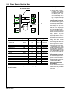
“OPT2” is a second input that may be used
with an external device, such as a gas flow
switch, to end the weld sequence. The gas
flow switch may be used to stop the weld se-
quence if shielding gas flow to the gun is inter-
rupted. A closed set of contacts between pins
1 and 2 of RC24 on Interface Board (PC20)
will allow feeder to operate normally. Opening
the contacts will stop the weld sequence and
display “ERR” in the upper display and
“OPT2” in the lower display.
Display Hold
Display hold indicated by ”DISP” in the upper
display is set to “OFF” or “HOLD” in the lower
display. When ”HOLD” is selected, the unit will
hold the last weld information for 5 seconds
following weld termination. If any front panel
push button is pressed, or if the Adjust control
is activated, the display hold feature is termi-
nated.
Software Revision Level
• If the Setup push button is pressed, the unit
displays the software version being used by
the interface PCB (PC20).
• When the Setup button is pressed again, the
menu repeats.
Code
Upon leaving the auxiliary menu, the user is
asked if a password code indicated by
“CODE” in the top display should be activated.
By default the code is off, indicated by “OFF”
in the lower display. The user may enter a nu-
merical password between 0 and 999 by turn-
ing the Adjust control. When the user re−en-
ters the auxiliary menu, the password code
must be selected to gain access to the auxilia-
ry menu. A failed attempt return the user to the
weld screen and a counter is incremented. A
counter in the program display shows the
number of incorrect attempts. The user has
five attempts to enter the correct password
code before being locked out of the auxiliary
menu, indicated by “LOCK” in the lower dis-
play . The power may be cycled to continue
welding but the user will remained locked out
of the auxiliary menu. Pressing the Program,
Sequence, upper display, and Set−up push
buttons simultaneously, the counter can be re-
set in the weld screen. Resetting the counter
is indicated by “CODE” in the upper display
and “RSET” in the lower display. Pressing the
Program, Sequence, upper display, and Set−
up push buttons simultaneously again will al-
low the user to reset the unit to the factory de-
faults, indicated by “WIPE” in the upper dis-
play. Resetting the unit will also turn off the
password code feature.
6-10 Auxiliary Menus (Continued)
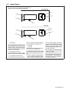
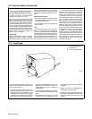
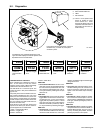
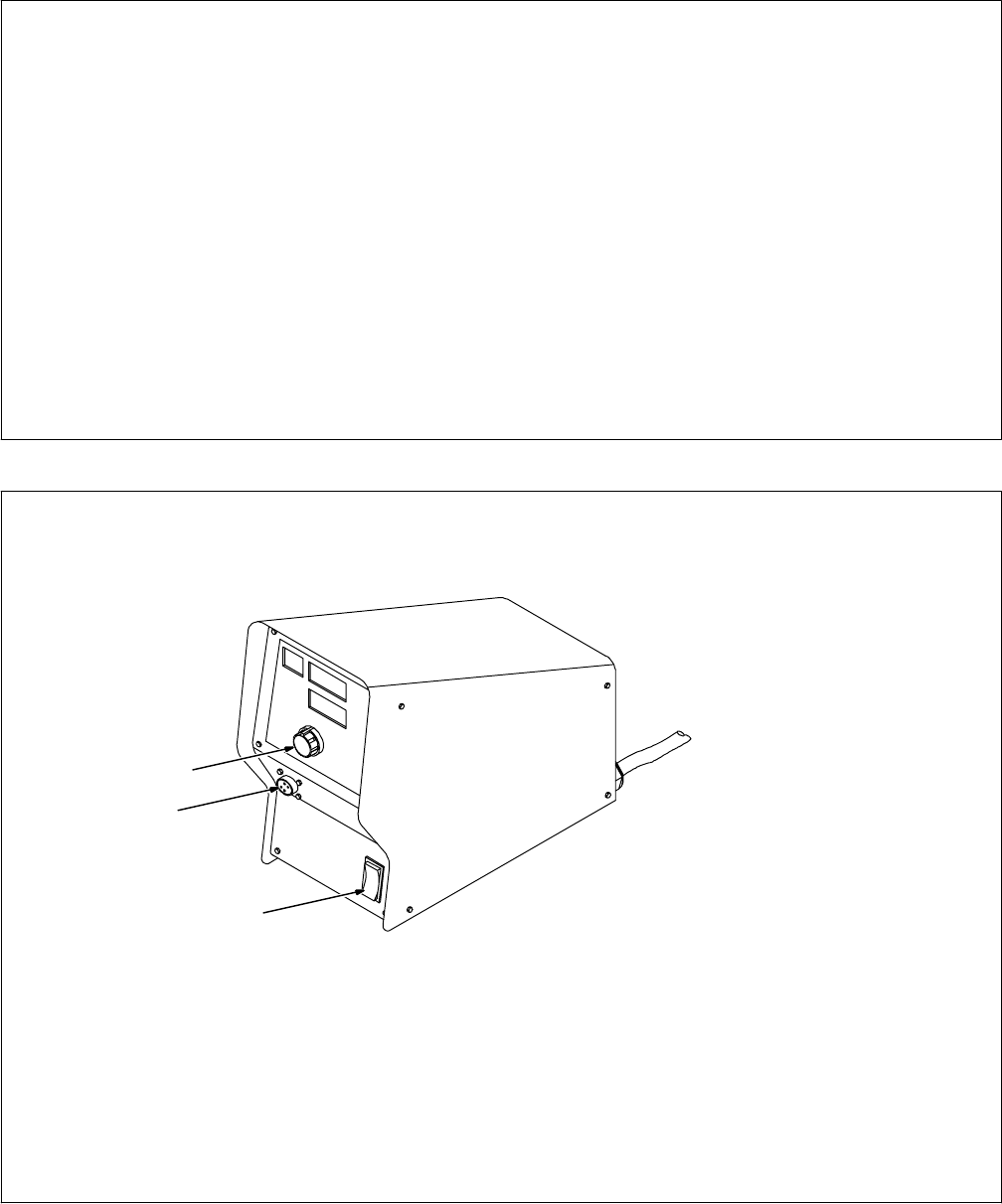
6-11. Jog/Purge
Pressing the Jog/Purge switch allows the op-
erator to jog wire without energizing the weld
power or gas valve circuit.
• The unit provides the ability to jog the wire
feeder by means of the gun trigger or the
Jog/Purge switch. If the welding arc does
not initiate in 3 seconds after the gun trigger
is activated, the unit will perform a jog opera-
tion for a maximum of two minutes. If the gun
trigger is still activated after two minutes, the
jog operation is terminated to prevent com-
plete despooling of the wire, in the case of
a damaged gun.
• The unit displays the “ERR TRIG“ message
to inform the operator that the trigger is acti-
vated.
• Jog speed can be adjusted by the Adjust
control when the unit is jogging wire. The
unit displays jog speed when the unit is be-
ing jogged.
• Jogging can also be accomplished by
pressing the Jog/Purge button.
• Pressing the Jog/Purge button also allows
the operator to purge gas lines before weld-
ing and to preset gas pressure at the
regulator.
1
802 807
2
3
1 Jog/Purge Push Button
2 Adjust Control
3 Gun Trigger Receptacle