


OM-1500-9 Page 27
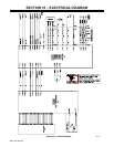
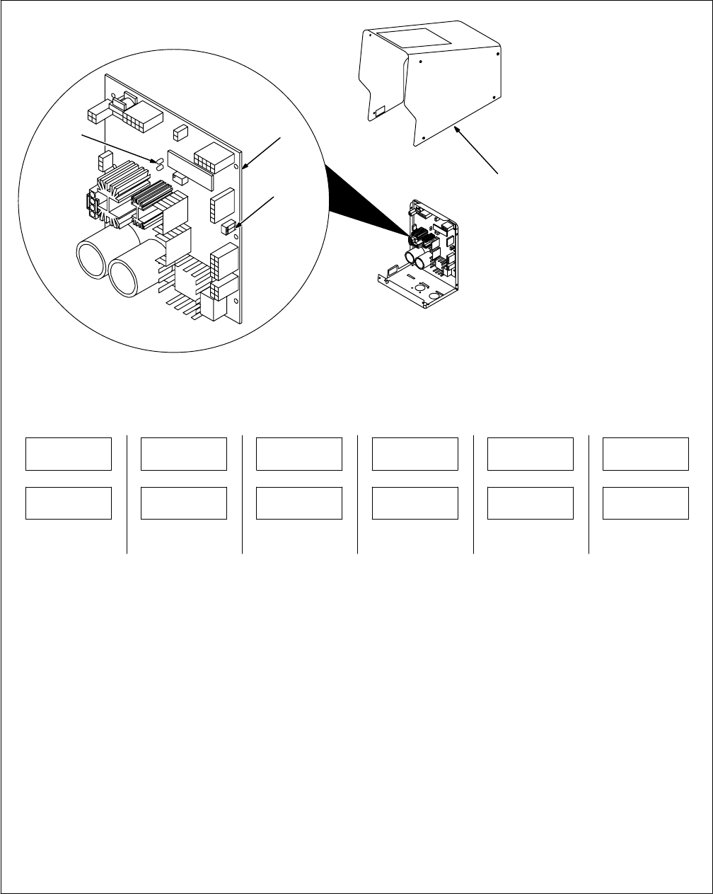
9-2. Diagnostics
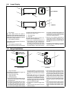
LED3-Related Error Indications
Error conditions are indicated by LED3 on
PC1. To view LED3, turn Off unit, remove
wrapper, and turn unit On. LED3 is most easily
observed from the left side of the unit.
The LED blinks in a 2.5 second cycle. The
number of blinks in this period indicates the
type of error.
The priority of the errors is related to the num-
ber of blinks indicating the error. The more
blinks, the more severe the error (motor error
is top priority). A higher priority error overrides
a lower one (if a motor error and a communica-
tion error existed, the light would blink four
times for the motor error).
Since blink On time and blink Off time are
equal in a four-blink cycle, the four−blink se-
quence appears as a constant blink.
1 blink = Communication Error
2 blinks = Trigger Error
3 blinks = Tach Error
4 blinks = Motor Error
ERR COM1
• The communication error occurs 2.5 sec-
onds after a loss of communication between
the motor and front panel boards. The user
may continue to weld with this error. The er-
ror may be cleared by resetting the unit (see
Section 6-10).
ERR TRG1
• The trigger error occurs if the user has the
trigger held for more than two minutes with-
out striking an arc, or if the user holds the
trigger past the postflow phase in a timed
weld. This error also occurs if the trigger is
held when the feeder is powered up. The er-
ror may be cleared by releasing the trigger.
ERR TCH1
• The tach error occurs 2 seconds after the
loss of tachometer feedback. The user may
continue to weld with this error. The motor
speed is regulated through the monitoring of
voltage and current.
ERR MTR1
• The motor error indicates that the motor
has been drawing too much current for too
long. To remedy this, reduce the wire feed
speed or the wire feeder torque load/duty
cycle.
ERR OPT1
• The optional 1 error indicates no coolant
flow in water flow switch option. The error
may be reset by reestablishing coolant flow
to the gun, and then pressing any button on
front panel.
ERR OPT2
• The optional 2 error indicates a problem
with optional device connected to RC24 on
Interface Board (PC20). The error may be
reset by correcting the problem, and then
pressing any button on front panel.
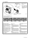
Ref. 802 687
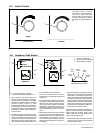
ERR
COM1
ERR
TRG1
ERR
TCH1
ERR
MTR1
The following error messages are shown on the
upper and lower displays to indicate specific errors.
Explanations are in the text below:
ERR
OPT1
ERR
OPT2
Indicates a
communication
error.
Indicates a trigger
error.
Indicates a
tachometer error.
Indicates a motor
error.
No gas flow
detected.
Optional error
condition.
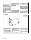
1
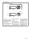
Front panel is shown removed for purpose of
illustration only. In actual use, front panel
would be in place.
3
1 Wrapper
2 Motor Control Board PC1
3 LED3
4 DIP Switch S1
. There is a two-position DIP
switch S1 located on motor
control board PC1. These
switches are factory-set in the
off position and must remain in
that position for the unit to op-
erate correctly.
2
4