


. A complete Parts List is available at www.MillerWelds.com
OM-225 216 Page 9
SECTION 3 − DEFINITIONS
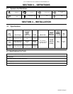
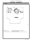
3-1. Symbols And Definitions
A
Amperes Increase Power Light
Low Air Pressure
Light
Loose Shield Cup
Light
Temperature Light On Off
SECTION 4 − INSTALLATION
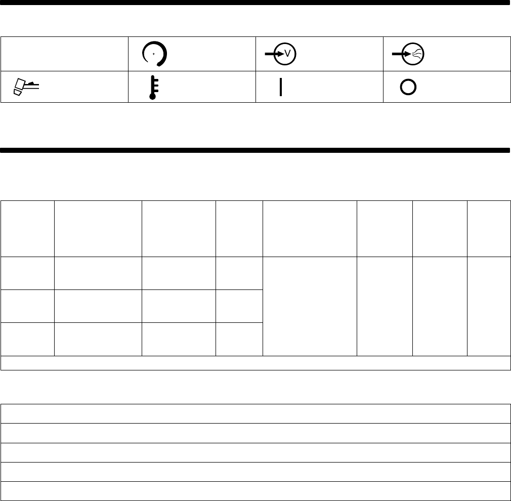
4-1. Specifications
Amperes Inpu
t
at Rated
Output,
Plasma
Rated
Cutting
Input
Voltage
Rated Output
Output,
60 Hz,
Single-Phase
KVA/KW Plasma Gas
Plasma
Gas Flow
/
Pressure
Cutting
Capacity
at 10 IPM
Max
OCV
120 Volts
±10%
(20 A)
27 A At 91 Volts DC
At 20% Duty Cycle
28.8 max;
0.30*
3.4 KVA
3.2 KW
4.5 CFM
120 Volts
±10%
(15 A)
20 A At 88 Volts DC
At 35% Duty Cycle
20.6 max;
0.30*
2.5 KVA
2.3 KW
Air Or Nitrogen
Only At 90−120 PSI
(621−827 kPa)
4.5 CFM
(129 L/min)
At 60 PSI
(414 kPa)
3/8 in
(10 mm)
400 Volts
DC
240 Volts
±10%
(27 A)
27 A At 91 Volts DC
At 35% Duty Cycle
13.9 max;
0.13*
3.3 KVA
3.0 KW
(621−827 kPa)
(414 kPa)
*While idling
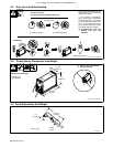
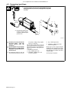
4-2. Specifications For Torch
Air-cooled torch for plasma arc cutting (PAC)
35% duty cycle
Safety interlock devices shut down power source
Safety trigger guard
Cutting capacity: see Section 4-1