


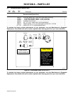


. A complete Parts List is available at www.MillerWelds.com
OM-225 216 Page 24
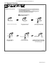
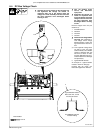
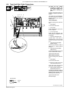
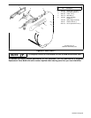
6-8. Torch And Work Cable Connections
Y Check DC bus voltage
according to Section 6-4,
and be sure voltage is near
zero before touching any
parts.
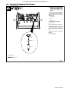
If torch or work cable needs to be
removed or replaced, proceed as
follows:
Turn power Off, and disconnect
input power plug from receptacle.
Remove wrapper from unit (see
Section 6-3).
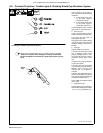
Torch Connections
Remove existing torch cable from
unit.
1 Strain Relief
Loosen strain relief screw.
2 Torch Cable
Insert cable through strain relief,
but do not tighten.
3 Air Line Connector
Insert air line connector into
solenoid fitting. Pull slightly on torch
to set fitting.
4 Plug PLG1/Receptacle RC1
Connect PLG1 from torch to
receptacle RC1 on end of wiring
harness connected to circuit board
PC1.
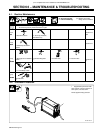
5 Ring Terminal And TORCH
WHITE Terminal
Connect ring terminal on end of
white leads to TORCH WHITE
terminal.
6 Ring Terminal And TORCH
RED Terminal
Connect ring terminal on end of red
leads to TORCH RED terminal.
Tighten strain relief screw.
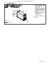
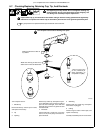
Work Cable Connections
Remove existing work cable from
unit.
7 Strain Relief
Loosen strain relief screw.
. Be sure to allow some work
cable slack inside the unit.
Insert work clamp lead through
strain relief, but do not tighten.
8 Work Lead Ring Terminal And
WORK BLACK Terminal
Connect ring terminal on end of
work clamp lead to terminal labeled
WORK BLACK terminal. Route
lead along torch lead bundle.
Tighten strain relief screw.
Reinstall wrapper.
Tools Needed:
Ref. 804 506-B / Ref. 802 860
1/4 in
Torx 25
3
2
4
5
1
2
7
8
6
4
5
3
6