


. A complete Parts List is available at www.MillerWelds.com
OM-225 216 Page 20
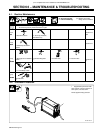
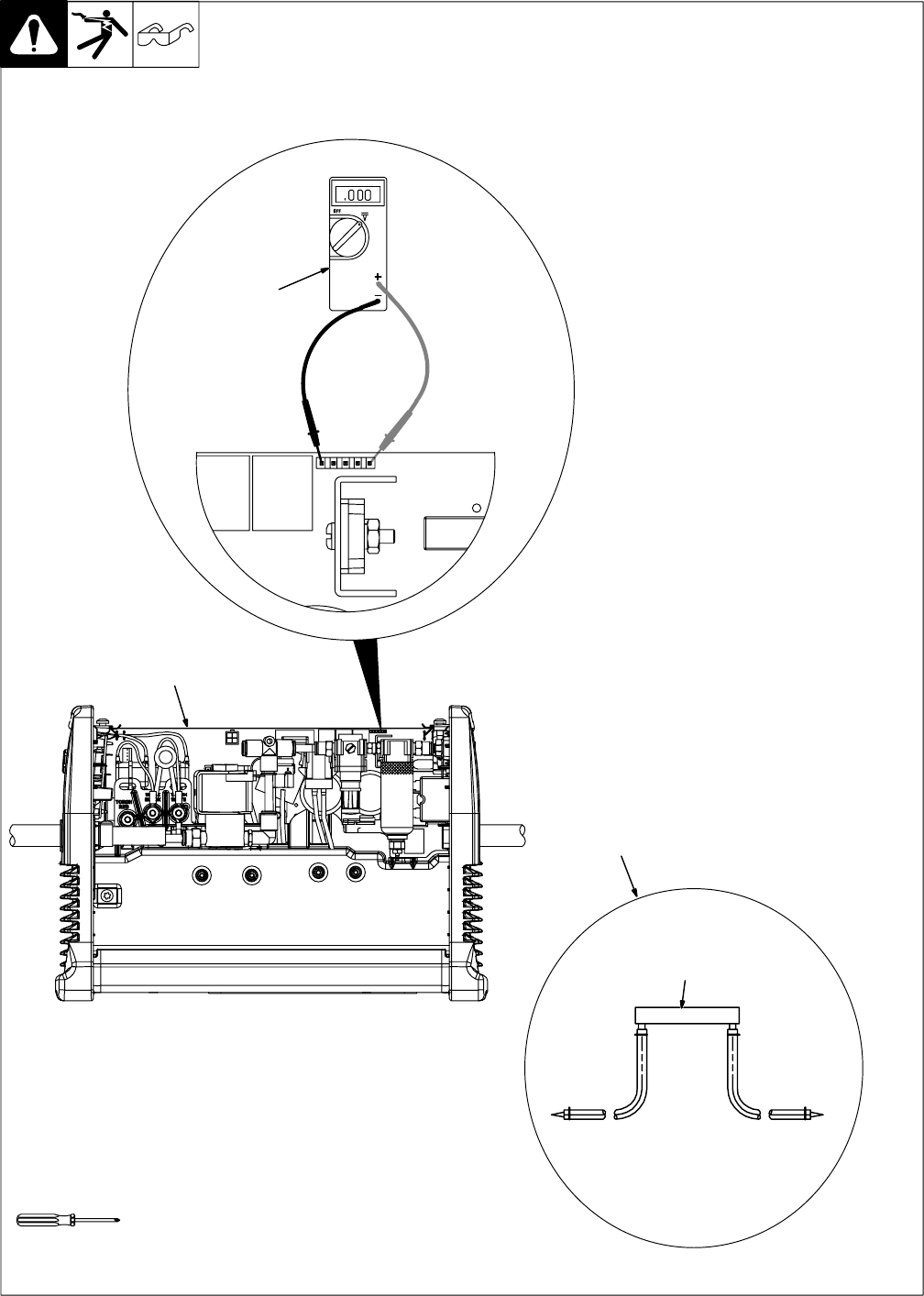
6-4. DC Bus Voltage Check
Y Turn Off welding power
source, and disconnect
input power.
Y Significant DC voltage can
remain on capacitors after
unit is Off. Always check the
voltage as shown to be sure
the input capacitors have
discharged before working
on unit.
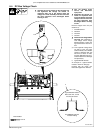
Remove wrapper from unit (see
Section 6-3).
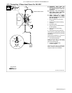
1 Circuit Board PC1
2 Voltmeter
3 TP5 Pin 5
4 TP5 Pin 1
Y Check DC bus voltage before
servicing. Set multimeter to
read voltage. Check voltage
between TP5 pins 1 and 5. Volt-
age should read 5 volts DC or
less.
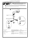
. If the capacitor voltage does
not drop to near zero after
several minutes, use a bleeder
resistor of between 200 and
500 ohms, at least 10 watts,
and #16 AWG 600 volts ac in-
sulation rated wire to discharge
the capacitor(s).
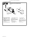
5 Typical Bleeder Resistor
An example of a typical bleeder
resistor is shown on this page.
Proceed with job inside unit.
Reinstall wrapper when finished.
Tools Needed:
Ref. 804 506-B
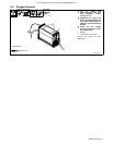
Y 440 Volts DC can be present on the capacitor bus
and significant DC voltage can remain on
capacitors after unit is Off. Always check the
voltage on inverter assembly as shown to be sure
the input capacitors have discharged before
working on unit.
5
Typical Bleeder Resistor
#16 AWG 600 Volts AC
Insulation Rating
200 to 500 ohm, 10 watt
wire wound resistor
Torx 25
1
2