


OM-2236 Page 15
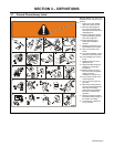
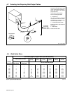
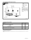
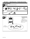
4-9. Connecting To Weld Output Terminals
Ref. 803 026-C
Tools Needed:
1
2
3/4 in
Y Turn off power before con-
necting to weld output
terminals.
1 Positive (+) Weld Output
Terminal
2 Negative (−) Weld Output
Terminal
3 Cable Restraint
Route weld cables through cable
restraint.
For DC Electrode Positive (DCEP),
connect work cable to negative (−)
terminal,and connect electrode
holder cable to positive (+) terminal.
For DC Electrode Negative
(DCEN), reverse cable
connections.
3
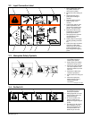
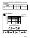
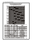
4-10. Electrical Service Guide
Input Voltage 220-230 440-460
Input Amperes At Rated Output 98 49
Max Recommended Standard Fuse Rating In Amperes
1
Time-Delay
2
100 50
Normal Operating 3 150 70
Min Input Conductor Size In AWG/Kcmil 4 8
Max Recommended Input Conductor Length In Feet (Meters)
148
(45)
258
(79)
Min Grounding Conductor Size In AWG/Kcmil 6 8
Reference: 1999 National Electrical Code (NEC)
1 Consult factory for circuit breaker applications.
2 “Time-Delay” fuses are UL class “RK5” .
3 “Normal Operating” (general purpose - no intentional delay) fuses are UL class “K5” (up to and including 60 amp), and UL class “H” ( 65 amp and
above).