


OM-2236 Page 18
SECTION 5 − OPERATION
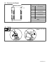
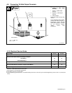
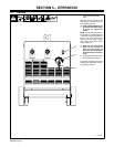
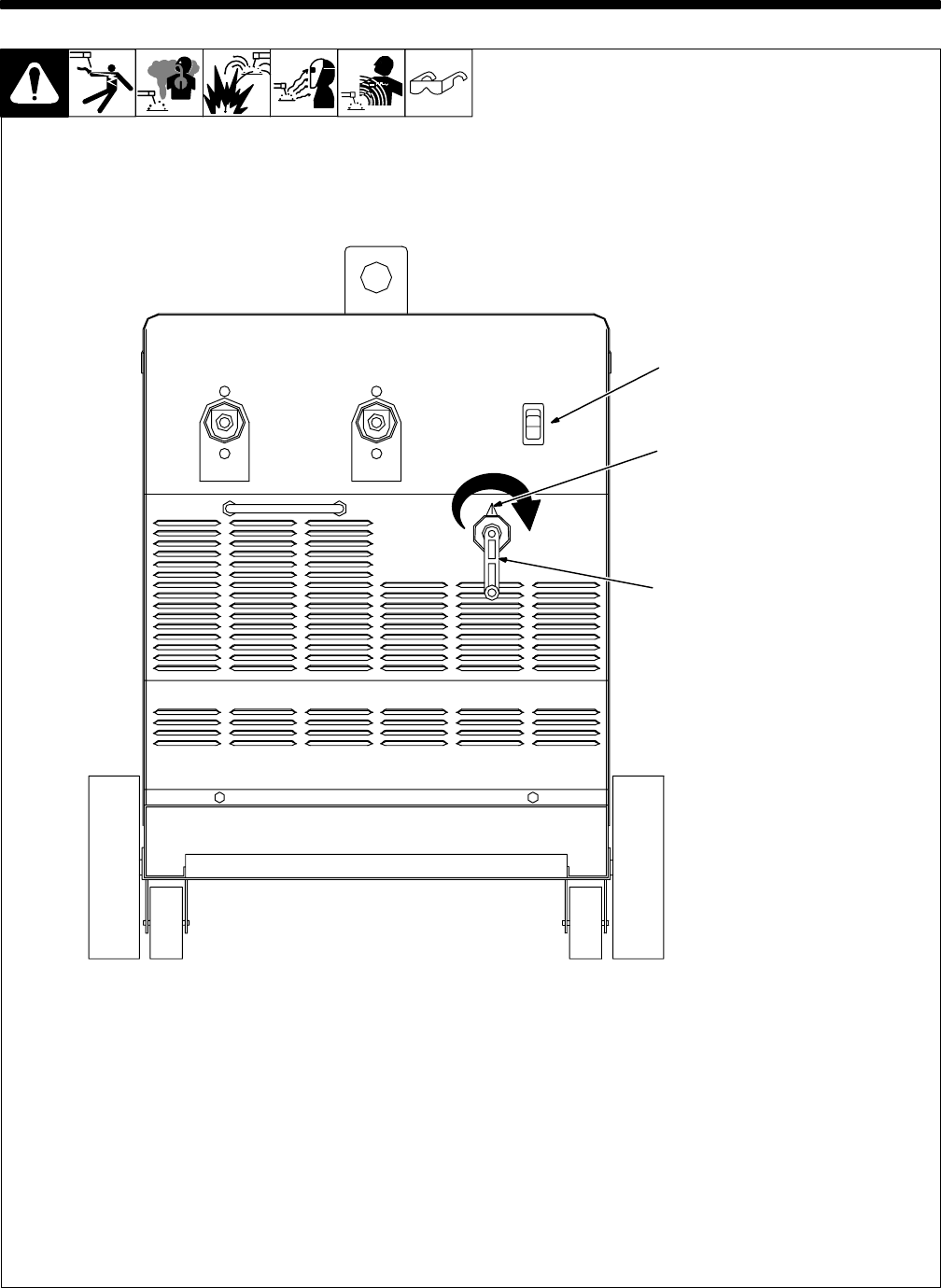
5-1. Controls
2
1
3
1 Power Switch W/Indicator
Lamp
When the switch is turned on, the
lamp lights to indicate power has
been applied to the unit.
Y If the indicator lamp does not
light when the power switch
is turned on, replace the
switch.
NOTE: This unit has over-tempera-
ture protection. If unit becomes hot
or if the duty cycle is exceeded (see
Section 4-2), weld output shuts
down and the fan stops running.
The indicator lamp on the power
switch remains on.
Y When the unit has cooled
down, the fan restarts air
flow, and weld output is
present at the weld output
terminals and/or at the elec-
trode.
2 Amperage Adjustment Control
3 Amperage Range Indicator
Turn handle clockwise to increase
amperage as indicated by the am-
perage range indicator.
803 026-C