


OM-353 Page 12
SECTION 3 – INSTALLATION
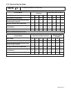
3-1. Specifications
Amperes Input at AC Balanced
Rated Load Output,
50/60 Hz, Single-Phase
Rated
Welding Output
PFC**
200 V 230 V 460 V 575 V
KVA KW
Amp
Range
Max
OCV
IP
Rating
NEMA Class II
(40) – 250
No
PFC
106
(4.6*)
92
(4*)
46
(2*)
37
(1.6*)
21
(0.89*)
11.4
(0.68*)
Amperes, 30 Volts
AC, 40% Duty
Cycle
With
PFC
76 66 33 26 15.2 11.4
5–310 A 80 V 21 S
*While idling
**Power Factor Correction
Rated
Amperes Input at AC Balanced
Rated Load Output,
50/60 Hz, Single-Phase
Rated
Welding
Output
PFC
**
200
V
220
V
230
V
260
V
380
V
415
V
460
V
520
V
575
V
KVA KW
Amp
Range
Max
OCV
IP
Rating
NEMA
Class I
(60) – 200
No
PFC
85
(4.6*)
77
(4.2*)
74
(4*)
65
(3.5*)
45
(2.4*)
41
(2.2*)
37
(2*)
33
(1.8*)
30
(1.6*)
17
(0.9*)
8.3
(0.7*)
Amperes,
28 Volts
AC, 60%
Duty Cycle
With
PFC
55
(57*)
64
(51*)
48
(49*)
48
(49*)
37
(30*)
34
(27*)
24
(25*)
48
(49*)
19
(20*)
11
(11*)
8.3
(0.6*)
5–310 A 80 V 21 S
*While idling
**Power Factor Correction
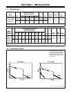
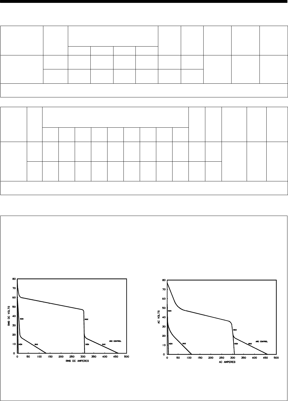
3-2. Volt-Ampere Curves
The volt-ampere curves show the
minimum and maximum voltage
and amperage output capabilities of
the welding power source. Curves
of other settings fall between the
curves shown.
ssb1.1 10/91 – SB-116 199 / SB-116 200
A. DC Mode
B. AC Mode