


OM-353 Page 14
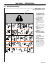
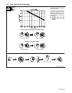
3-4. Selecting A Location
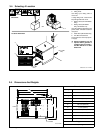
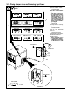
1 Lifting Eye
2 Lifting Forks
Use lifting eye or lifting forks to
move unit.
If using lifting forks, extend forks
beyond opposite side of unit.
3 Rating Label (Non CE Models
Only)
4 Rating Label (CE Models
Only, See Section 2-2)
Use rating label to determine input
power needs. CE label located on
rear panel.
5 Plate Label (CE Models Only)
6 Line Disconnect Device
Locate unit near correct input pow-
er supply.
Y Special installation may be
required where gasoline or
volatile liquids are present –
see NEC Article 511 or CEC
Section 20.
1
2
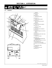
Movement
ST-800 402 / ST-117 264-F
6
18 in (460
mm)
Location And Airflow
OR
18 in (460
mm)
3
5
4
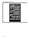
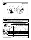
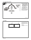
3-5. Dimensions And Weights
Dimensions
A
Height 30-3/4 in (781 mm)
B
C
Width 19-3/4 in (502 mm)
E
D
Length 27-1/2 in (698 mm)
A 27 in (686 mm)
B 26 in (661 mm)
F
C 25-1/4 in (642 mm)
F
Front
D 1-1/2 in (38 mm)
G
E 1-1/8 (29 mm)
F 17-7/8 (454 mm)
G 19-1/4 (489 mm)
H 1/2 in (13 mm) Dia
6 Holes
H
Weight
ST-154 792-B
355 lbs (161 kg)