


OM-2251 Page 13
SECTION 4 − INSTALLATION
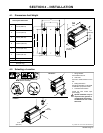
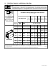
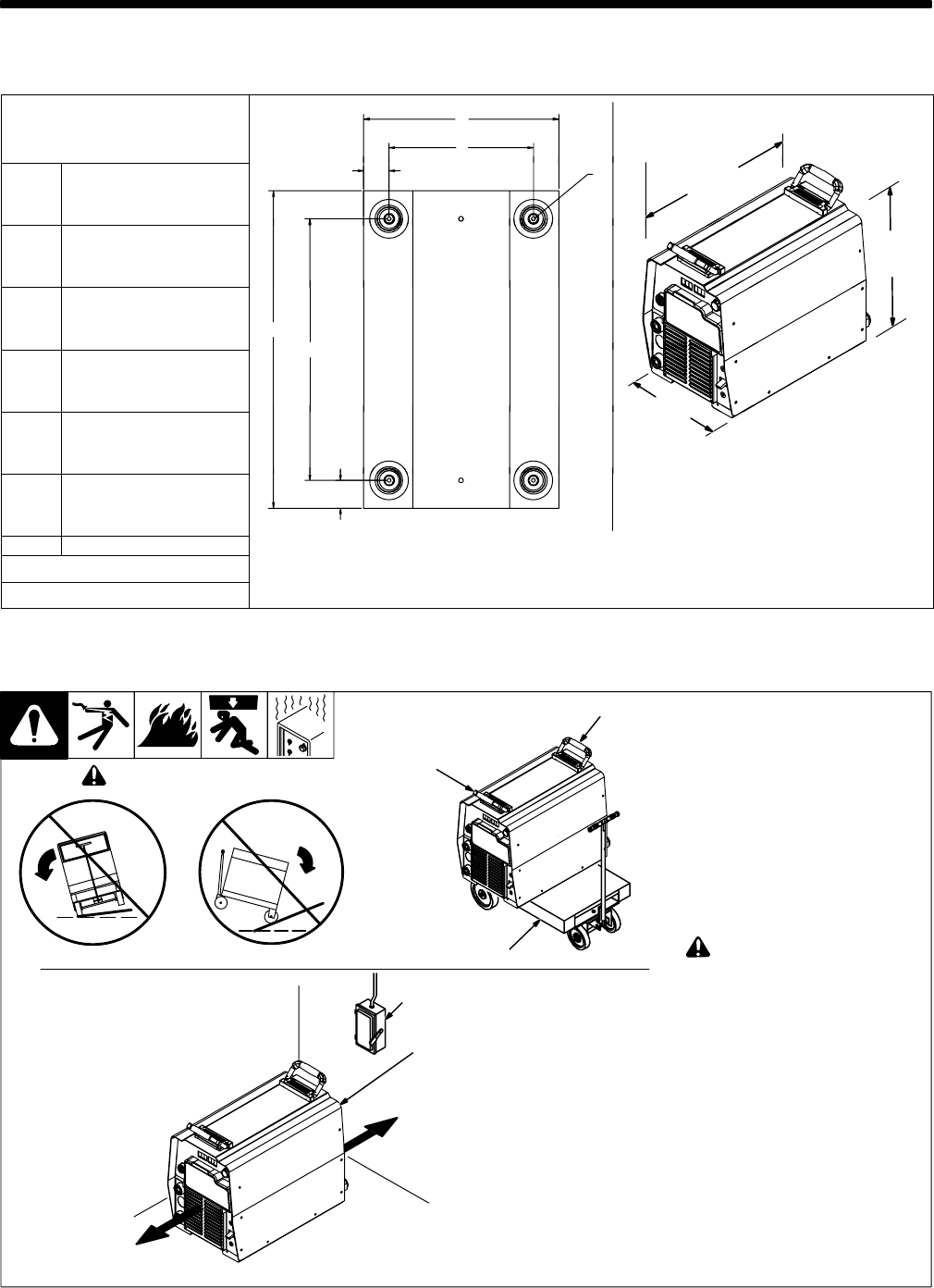
4-1. Dimensions And Weight
Hole Layout Dimensions
24 in
(610
A
E
A 11-3/4 in (298 mm)
(610
mm)
G
F
B 1-11/16 in (42 mm)
17 in
(432 mm)
C 15-3/4 in (400 mm)
D
C
D 19-3/32 in (485 mm)
C
E 8-11/16 in (221 mm)
12-1/2 in
(318 mm)
F 1-17/32 in (39 mm)
804 801-A
B
G 1/4-20 UNC -2B thread
Weight
80 lb (36.3 kg)
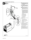
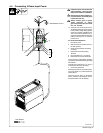
4-2. Selecting a Location
loc_2 3/96 - Ref. ST-151 556 / Ref. 803 691-C
1 Lifting Handles
Use handles to lift unit.
2 Hand Cart
Use cart or similar device to move
unit.
3 Rating Information
Use rating information on rear panel
to determine input power needs.
4 Line Disconnect Device
Locate unit near correct input
power supply.
! Special installation may be
required where gasoline or
volatile liquids are present −
see NEC Article 511 or CEC
Section 20.
Movement
1
2
! Do not move or operate unit
where it could tip.
Location
4
3
18 in
(460 mm)
18 in
(460 mm)
1