


OM-2251 Page 14
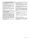
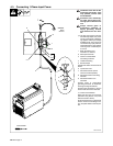
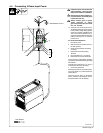
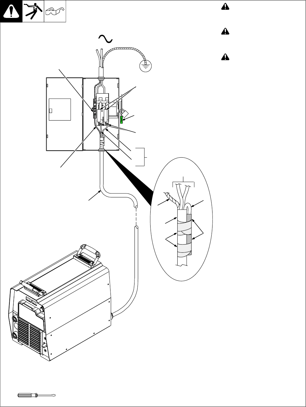
4-3. Connecting 1-Phase Input Power
Ref. 804 532-A
! Installation must meet all Na-
tional and Local Codes − have
only qualified persons make
this installation.
! Disconnect and lockout/tag-
out input power before con-
necting input conductors from
unit.
! Always connect green or
green/yellow conductor to
supply grounding terminal
first, and never to a line termi-
nal.
. The Auto-Line circuitry in this unit
automatically adapts the power
source to the primary voltage be-
ing applied. Check input voltage
available at site. This unit can be
connected to any input power be-
tween 208 and 575 VAC without
removing cover to relink the pow-
er source.
1 Black And White Input
Conductor (L1 And L2)
2 Red Input Conductor
3 Green Or Green/Yellow
Grounding Conductor
4 Insulation Sleeving
5 Electrical Tape
Insulate and isolate red conductor as
shown.
6 Input Power Cord.
7 Disconnect Device (switch
shown in the OFF position)
8 Disconnect Device Grounding
Terminal
9 Disconnect Device Line
Terminals
Connect green or green/yellow
grounding conductor to disconnect
device grounding terminal first.
Connect input conductors L1 and L2
to disconnect device line terminals.
10 Overcurrent Protection
Select type and size of overcurrent
protection using Section 4-5 (fused
disconnect switch shown).
Close and secure door on disconnect
device. Remove lockout/tagout de-
vice, and place switch in the On posi-
tion.
7
6
L1
L2
1
=GND/PE
Earth
Ground
3
1
8
9
10
Tools Needed:
1
6
5
4
2
3