


OM-2251 Page 18
‘
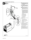
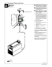
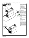
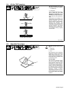
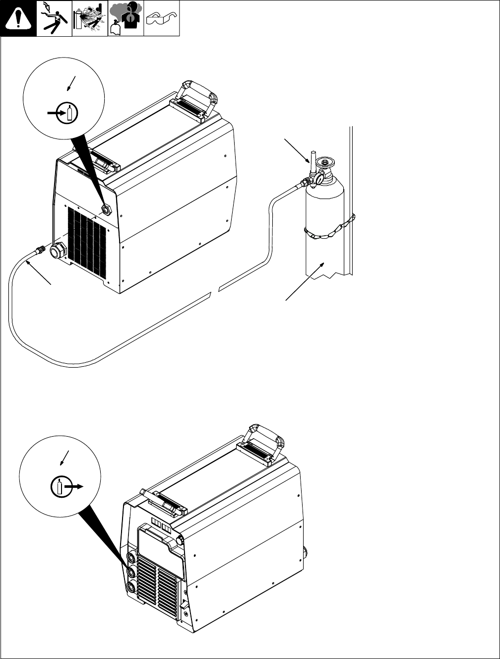
4-7. Optional Gas Valve Operation And Shielding Gas Connection
Obtain gas cylinder and chain to
running gear, wall, or other station-
ary support so cylinder cannot fall
and break off valve.
1 Cylinder
2 Regulator/Flowmeter
Install so face is vertical.
3 Gas Hose Connection
Fitting has 5/8-18 right-hand
threads. Obtain and install gas
hose.
4 Gas In Fitting
5 Gas Out Fitting
The Gas In and Gas Out fittings
have 5/8-18 right-hand threads.
Obtain proper size, type, and length
hose and make connections as fol-
lows:
Connect hose from shielding gas
supply regulator/flowmeter to Gas
In fitting.
Connect hose coupler to torch.
Connect one end of gas hose to
hose coupler. Connect remaining
end of gas hose to Gas Out fitting.
Operation
The gas solenoid controls gas flow
during the TIG process as follows:
Lift−Arc TIG
Gas flow starts when tungsten
touches work (touch sensed).
Gas flow stops at end of post−flow.
Scratch Start TIG
Gas flow starts when current is de-
tected.
Gas flow stops at end of post−flow.
Post−flow time is factory set to 5
seconds per 100 amps of weld cur-
rent. The minimum post−flow time
is 5 seconds. The maximum post−
flow is 20 seconds (post flow set-
tings are not adjustable by the end
user).
4
3
1
2
GAS IN
GAS OUT
5
Ref. 803 728-B / 804 533-A