


OM-815 Page 10
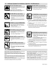
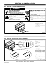
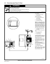
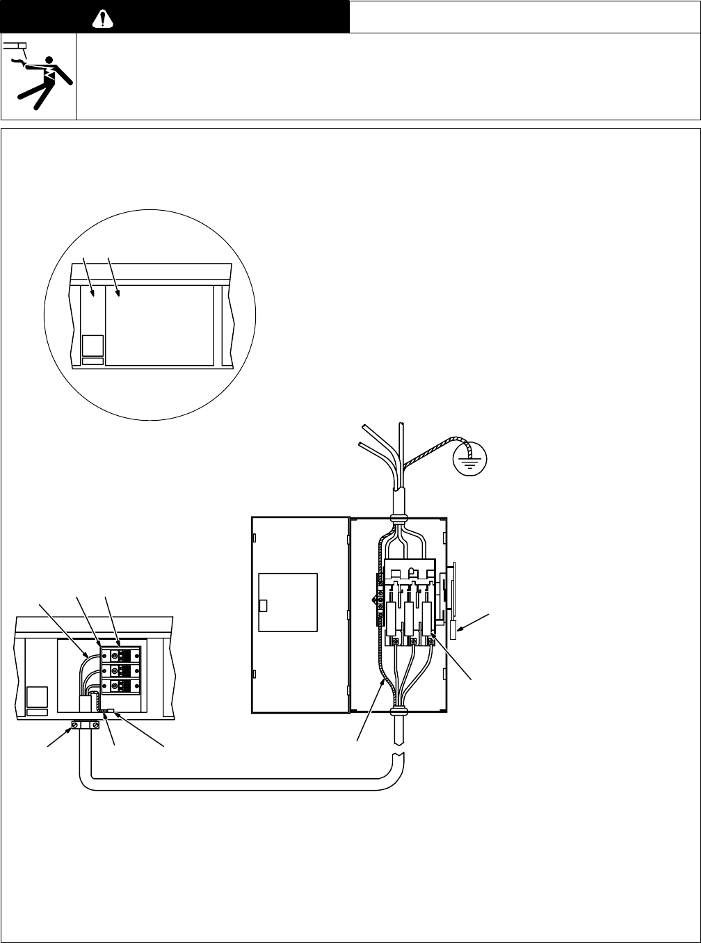
4-6. Connecting Input Power To Rack
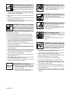
WARNING
ELECTRIC SHOCK can kill.
• Do not touch live electrical parts.
• Turn Off welding power sources before inspecting or installing rack.
• Have only qualified persons install rack.
• Installation must meet National Electrical Code and all other codes.
swarn3.1* 2/93
Have only qualified persons make
this installation.
1 Rear Control Box Center
2 Access Panel
Remove access panel.
3 Line Disconnect Device Of
Proper Rating
4 Input Conductors
5 Grounding Conductor
Select size and length using
Table 4-2. Conductors must be
able to carry the combined amper-
age draw of all welding power
sources mounted on the rack. Con-
ductor insulation must comply with
national, state, and local electrical
codes. Use lugs of proper amper-
age capacity and correct hole size.
6 User-Supplied Strain Relief
Connector
Insert conductors through strain
relief.
7 Input Terminal Block
8 Line Terminals
9 Ground Terminal
Connect grounding conductor to
ground terminal first. Then connect
input conductors to line terminals.
Reinstall access panel.
Install grounding conductor and in-
put conductors in conduit or equiv-
alent to deenergized line discon-
nect device.
Connect grounding conductor first,
then line input conductors.
Be sure grounding conductor goes
to an earth ground.
10 Overcurrent Protection
Select type and size using
Table 4-2. Install into deenergized
line disconnect device (fused
disconnect switch shown).
1 2
7
8
4
6 95
3
10
ST-151 270-C
5
Figure 4-6. Input Power Connections