


76
TOOL ASSEMBLY
To reduce the risk of injury, al-
ways unplug tool before attaching
or removing accessories. Use
only specifically recommended
accessories. Others may be
hazardous.
WARNING!
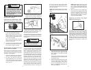
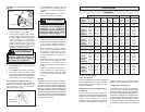
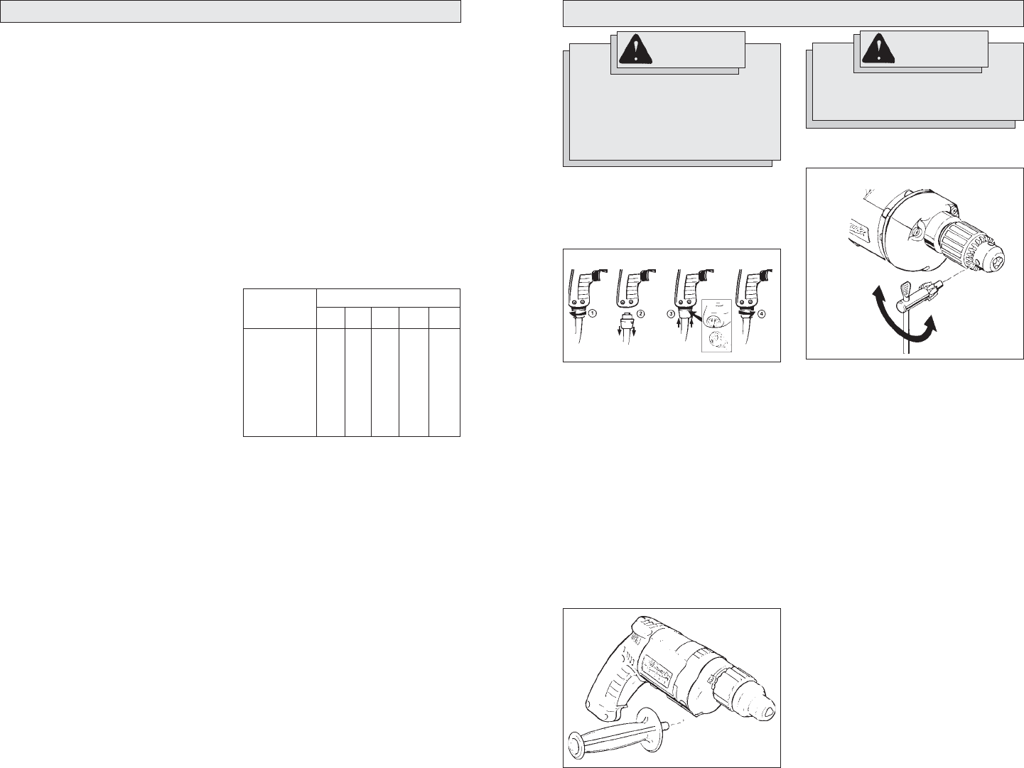
Removing and Replacing Quik-Lok
®
Cords (Fig. 1)
MILWAUKEE's exclusive Quik-Lok
®
Cords
provide instant field replacement or
substitution.
Fig. 1
1. To remove the Quik-Lok
®
Cord, turn the
cord nut 1/4 turn to the left and pull it
out.
2. To replace the Quik-Lok
®
Cord, align the
connector keyways and push the con-
nector in as far as it will go. Turn the
cord nut 1/4 turn to the right to lock.
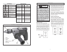
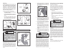
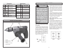
Installing Side Handle (Fig. 2)
MILWAUKEE Magnum Drills are supplied
with a side handle that can be installed on
either side of the tool for right or left handed
use. To install the side handle, thread it into
the socket on the desired side of the tool
and tighten it securely. Always use the side
handle for best control.
To prevent personal injury, al-
ways remove the chuck key from
the chuck after each use.
WARNING!
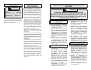
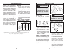
Installing Bits into Keyed Chucks (Fig. 3)
Cat. No. 0234-1, 0244-1
1. Open the chuck jaws wide enough to
insert the bit. Be sure the bit shank and
chuck jaws are clean. Dirt particles may
prevent the bit from lining up
properly.
2. When using drill bits, insert the bit into
the chuck. Center the bit in the chuck
jaws and lift it about 1/16" off of the
bottom. Tighten the chuck jaws by hand
to align the bit.
When using screwdriver bits, insert the
bit far enough for the chuck jaws to
grip the bit shank. Tighten the chuck
jaws by hand to align the bit.
3. Place the chuck key in each of the three
holes in the chuck, turning it clockwise
as shown. Tighten securely.
4. To remove the bit, insert the chuck key
into one of the holes in the chuck and
turn it counterclockwise.
Fig. 2
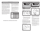
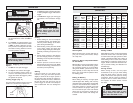
Grounded tools require a three wire ex-
tension cord. Double insulated tools can
use either a two or three wire extension
cord. As the distance from the supply out-
let increases, you must use a heavier
gauge extension cord. Using extension
cords with inadequately sized wire causes
a serious drop in voltage, resulting in loss
of power and possible tool damage. Refer
to the table shown to determine the re-
quired minimum wire size.
The smaller the gauge number of the wire,
the greater the capacity of the cord. For
example, a 14 gauge cord can carry a
higher current than a 16 gauge cord. When
using more than one extension cord to make
up the total length, be sure each cord con-
tains at least the minimum wire size re-
quired. If you are using one extension cord
for more than one tool, add the nameplate
amperes and use the sum to determine the
required minimum wire size.
Guidelines for Using Extension Cords
• If you are using an extension cord out-
doors, be sure it is marked with the
suffix “W-A” (“W” in Canada) to indi-
cate that it is acceptable for outdoor
use.
• Be sure your extension cord is prop-
erly wired and in good electrical
condition. Always replace a damaged
extension cord or have it repaired by a
qualified person before using it.
• Protect your extension cords from
sharp objects, excessive heat and
damp or wet areas.
READ AND SAVE ALL INSTRUCTIONS FOR FUTURE USE.
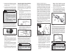
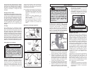
Recommended Minimum Wire
Gauge for Extension Cords*
Extension Cord Length
* Based on limiting the line voltage drop to
five volts at 150% of the rated amperes.
Nameplate
Amperes
0 - 2.0
2.1 - 3.4
3.5 - 5.0
5.1 - 7.0
7.1 - 12.0
12.1 - 16.0
16.1 - 20.0
25'
18
18
18
18
16
14
12
75'
18
18
16
14
12
10
100'
18
16
14
12
10
150'
16
14
12
12
50'
18
18
18
16
14
12
10
EXTENSION CORDS
Tighten
Loosen
Fig. 3