


98
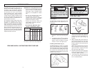
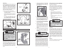
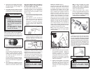
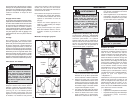
Chuck Removal (Fig. 7)
This tool is equipped with a threaded spindle
to hold the chuck. Before removing the
chuck, unplug the tool and open the chuck
jaws. A left-handed thread screw is lo-
cated inside the chuck to prevent the chuck
from loosening when the tool is operated
in reverse direction. Remove the screw by
turning it clockwise. To remove the chuck,
hold the tool so that only the side of the
chuck rests firmly and squarely on a solid
workbench. Insert the chuck key or a chuck
remover bar in one of the keyholes. Turn
the chuck so the key is at about a 30° angle
to the bench top and strike the key sharply
with a hammer so the chuck turns in a
counterclockwise direction (looking from
WARNING!
To reduce the risk of injury, al-
ways wear eye protection.
Fig. 7
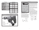
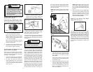
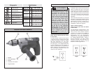
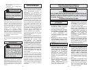
Installing Bits into Keyless Chucks
(Fig. 4) Cat. No. 0233-20
These tools are equipped with a hand-
tightening keyless chuck. Always unplug
the tool before installing or removing bits.
3. To close the chuck jaws, turn the chuck
sleeve in clockwise direction (Fig. 6).
Tighten securely. Several detents will
be felt as the chuck sleeve is turned.
1. To open the chuck jaws, turn the sleeve
in the counterclockwise direction.
When using drill bits, allow the bit to
strike the bottom of the chuck. Center
the bit in the chuck jaws and lift it about
1/16" off of the bottom.
When using screwdriver bits, insert the
bit far enough for the chuck jaws to
grip the hex of the bit.
2. To close the chuck jaws, hold the collar
while turning the sleeve in the clock-
wise direction. Tighten securely.
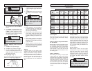
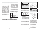
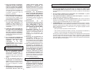
Installing Bits into Keyless Chucks
(Fig. 5 & 6) Cat. No. 0235-21
These tools are equipped with a spindle-
lock mechanism and a single-sleeve key-
less chuck. Always unplug the tool before
inserting or removing bits.
1. To open the chuck jaws, turn the chuck
sleeve in counterclockwise direction.
2. To install a bit, open the chuck jaws
slightly wider than the bit. Center the bit
in the chuck jaws and lift it about
1/16" off of the bottom. Align the bit as
shown (Fig. 5).
To reduce the risk of injury:
• Do not grasp the bit while the
chuck is rotating or while the
bit is falling from the chuck.
• Release the trigger as soon as
the ratcheting stops to avoid
throwing the bit.
WARNING!
Fig. 5
Fig. 6
Sleeve
To close
NOTE: If the spindle rotates when opening
or closing the chuck jaws, grasp the chuck
and slightly rotate back and forth to en-
gage the spindle-lock mechanism.
The spindle will remain locked until the tool
is turned on. The spindle-lock mechanism
will automatically disengage when the tool
is turned on.
Collar
Sleeve
Fig. 4
Cat. No. 0233-20
the front of the tool). This should loosen
the chuck from the spindle which has a
right hand thread making it easy to remove
the chuck by hand.
NOTE: When replacing the chuck, always
replace the left hand thread screw in the
chuck.
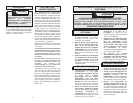
Attaching Right Angle Drive to Drill
(Fig. 8)
Fig. 9
Fig. 8
1
2
3
4
5
1. Remove the chuck from the drill follow-
ing instructions (See “Removing the
Chuck From the Drill”). Slip the double
hex coupling (1) over the hex on the
drill spindle.
Loosen the clamping screws on the
clamping sleeve (2) and slip the sleeve
onto the drill collar.
2. Slide the Right Angle Drive head (4) into
the other side of the sleeve and turn
the drive head slightly in either direc-
tion so the hexagonal hole in the cou-
pling (1) engages the hexagonal por-
tion of the spindle (3).
The chuck can be removed from the Right
Angle Drive Unit in the same manner it is
removed from the drill; however, ALWAYS
REMOVE RIGHT ANGLE DRIVE FROM THE
DRILL BEFORE ATTEMPTING TO LOOSEN
THE CHUCK. This will prevent damaging
the drill's gearing. Use the open end wrench
provided to hold the Right Angle Drive
spindle before attempting to loosen the
chuck.
NOTE: Attaching the drill chuck to the
side marked “LOW” reduces the speed
by 1/3, or 33%. Attaching the drill chuck
to the opposite side increases the speed
by 50%.
3. When assembled, turn the Right Angle
Drive head to the desired position and
tighten the clamping screws to secure
the unit. Thread the chuck onto the
Right Angle Drive spindle (5). INSTALL
CHUCK LOCKING SCREW.
Removing the Chuck From Right
Angle Drive Unit (Fig. 9)