


10 11
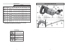
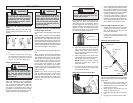
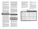
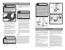
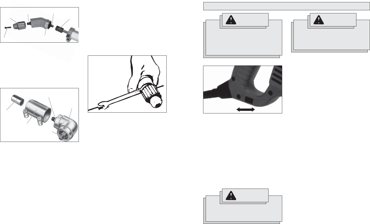
Attaching 33° Angle Drive
Hex
socket
Fig. 5
Hex drive
Clamp
1. Attach 33° angle drive by inserting hex
drive into hex socket in extension drive
shaft. Secure with clamp.
2. Thread the chuck onto the 33° angle
drive spindle. INSTALL CHUCK LOCK-
ING SCREW.
Locking screw
Chuck
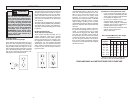
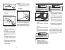
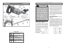
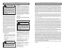
Attaching Right Angle Drive to Drill
1. Remove the chuck from the drill (see
“Removing the Chuck From the Drill”).
Slip the double hex coupling over the
hex on the drill spindle.
Loosen the clamping screws on the
clamping sleeve and slip the sleeve onto
the drill collar.
2. Slide the Right Angle Drive head into
the other side of the sleeve and turn
the drive head slightly in either direction
so the hexagonal hole in the coupling
engages the hexagonal portion of the
spindle.
NOTE: Attaching the drill chuck to the
side marked “LOW” reduces the speed
by 1/3, or 33%. Attaching the drill chuck
to the opposite side increases the speed
by 50%.
3. When assembled, turn the Right Angle
Drive head to the desired position and
tighten the clamping screws to secure
the unit. Thread the chuck onto the Right
Angle Drive spindle. INSTALL CHUCK
LOCKING SCREW.
Fig. 6
Double
hex coupling
Clamping
sleeve
Drill
head
Spindle
hexagon
Right Angle
Drive Spindle
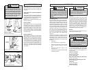
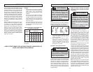
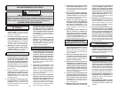
Removing Chuck From Angle Drive Units
The chuck can be removed from the angle
drive unit in the same manner it is removed
from the drill; however, ALWAYS REMOVE
ANGLE DRIVE FROM THE DRILL BEFORE
ATTEMPTING TO LOOSEN THE CHUCK.
This will prevent damaging the drill's gearing.
Use the open end wrench provided to hold
the angle drive spindle before attempting to
loosen the chuck.
Fig. 7
Spindle
Attaching Right Angle Drive to 30" Exten-
sion Tube
1. Attach right angle drive by inserting
spindle hexagon into hex socket in ex-
tension drive shaft. Secure with clamp.
2. Thread the chuck onto the right angle
drive spindle. INSTALL CHUCK LOCK-
ING SCREW.
WARNING
To reduce the risk of injury, wear
safety goggles or glasses with side
shields. Unplug the tool before
changing accessories or making
adjustments.
OPERATION
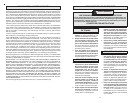
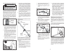
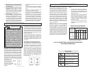
Using Forward/Reverse Switch
Fig. 8
forwardreverse
1. For forward (clockwise) rotation, push
the forward/reverse switch to FWD as
shown.
Check the direction of rotation before
use.
2. For reverse (counterclockwise) rotation,
push the forward/reverse switch to REV
as shown.
Check the direction of rotation before
use.
Although an interlock prevents reversing
the tool while the motor is running, allow
the motor to come to a full stop before
reversing.
Starting, Stopping and Controlling
Speed
1. To start the tool, pull trigger.
2. To stop the tool, release the trigger.
3. To vary the speed, increase or decrease
pressure to the trigger. The further the
trigger is pulled, the greater the speed.
Drilling
1. Before drilling, be sure the workpiece is
clamped securely. Use backing material
to prevent damage to the workpiece
during breakthrough.
2. When starting a hole, place the drill
bit on the work surface and apply fi rm
pressure. Begin drilling at a slow speed,
gradually increasing the speed as you
drill.
3. Always apply pressure in line with the bit.
Use enough pressure to keep the drill
biting, but do not push hard enough to
stall the motor.
4. Reduce pressure and ease the bit
through the last part of the hole. While
the tool is still running, pull the bit out of
the hole to prevent jamming.
Stalling
If the tool seems as if it is about to stall, main-
tain a fi rm grip and reduce pressure slightly
to allow the bit to regain speed. If the tool
does stall, release the trigger immediately.
Reverse the motor, remove the bit from the
work and start again. Do not pull the trigger
on and off in an attempt to start a stalled drill.
This can damage the drill.
WARNING
To reduce the risk of injury, keep
hands and cord away from the bit
and all moving parts.
WARNING
To reduce the risk of explosion, elec-
tric shock and property damage, al-
ways check the work area for hidden
pipes and wires before drilling.