


4
5
V
O
R
E
C
O
T
T
A
L
E
E
T
D
G
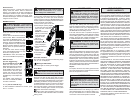
FUNCTIONAL DESCRIPTION
ASSEMBLY
WARNING Recharge only with the char-
ger specifi ed for the battery. For specifi c charg-
ing instructions, read the operator’s manual
supplied with your charger and battery.
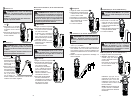
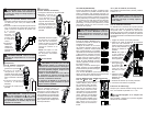
Inserting/Removing the Battery
To remove the bat-
tery, use a fl at screw-
driver to pry open the
lock latch. Push in the
release buttons and
pull the battery pack
away from the tool.
To insert the battery,
slide the pack into the body of the tool. Make sure
it latches securely into place. Press in the lock latch
to lock the battery in place.
Symbology
To reduce the risk of injury, user must
read operator’s manual.
Double insulation
Risk of electric shock
Indicates that this instrument can clamp
on bare conductors when measuring a
voltage corresponding to the applicable
measurement category, which is marked
next to this symbol.
Earth
Danger, Warning, or Caution - Consult
the operators manual for additional
safety information.
Volts Direct Current
European Conformity Mark
Underwriters Laboratories, Inc.,
United States and Canada
Cat III
Classifi cation of transient overvoltages,
based on nominal line voltage to earth.
Cat IV
Do not dispose of this product as
unsorted municipal waste.
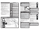
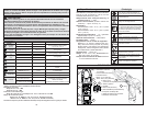
1. Current sensing jaws
2. NCVD sensing area
3. NCVD indicator
4. °F/°C button (2238-20)
Zero button (2239-20)
5. Inrush button (2239-20)
Cat. No.
2238-20
Cat. No.
2239-20
6. Rotary Dial
7. Display
8. Hold button
9. Min/Max button
10. Worklight LED
11. Jaw opening trigger
12. Terminal inputs
2
4
11
12
6
10
8
7
5
3
9
6
1
Lock latch
Fig. 1
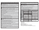
General Specifi cations
Accuracy is specifi ed for 1 year after calibration,
at operating temperatures of 18°C to 28°C (64°F
to 82°F), with relative humidity at 0 % to 85 %.
Maximum voltage between any terminal and
earth ground .... 1000 V
Jaw Opening (maximum conductor size) ....
approx. 1.3” (33 mm)
Temperature ....
Operating: -10°C to 50°C (14°F to 122°F)
Storage: -40°C to 60 °C (-40°F to 140°F)
Temperature Coeffi cient .... 0.1 x (specifi ed
accuracy)/°C (<18°C or >28°C)
Operating Altitude.... 2,000 meters
Drop Test .... 1 meter
Safety Compliances .... EN61010-1,
UL 61010-1, EN61010-031 (Probes),
IEC 61010-2-32 (Clamp Assemblies),
IEC/EN 61010-1 2nd Edition for measurement
Category III, 1000 V, Category IV, 600 V,
Pollution Degree 2, EMC EN61326-1
Certifi cations .... cULus, CE
Voltage: 12 DC Li-Ion, MILWAUKEE Battery
Pack Cat. Nos. 48-11-2401, 48-11-2402
Battery run time: Greater than 12 hrs with all
functions
OPERATION
WARNING Always turn the Rotary
Dial to OFF before inserting or removing
probes. Only use accessories specifi cally
recommended for this tool. Others may be
hazardous.
DANGER To avoid electrical shock:
Never make measurement on a circuit in
which voltage over 1000V exists. Clamp tips
are designed not to short the circuit under
test. If equipment under test has exposed
conductive parts, however, extra precaution
should be taken to minimize the possibility
of shorting.
Disconnect the test leads from the instrument
for current measurement.
Before Use
Confi rm the Rotary Dial is set to the correct position,
the instrument is set to the correct measurement
mode, and the Data hold function is disabled. Oth-
erwise, desired measurement cannot be made.
Making a Measurement
AC Current
WARNING
Only use MILWAUKEE test leads with the
MILWAUKEE Clamp Meters.
Inspect test leads before each use. Use clamp
meter to run a continuity test.
1. Set the Rotary Dial to position.
AC mark is displayed.
2. Press the jaw opening trigger to
open the jaws and clamp them
onto the conductor under test. The
reading is displayed.
NOTE: Do not clamp over 2 or more
wires at the same time. Irregular
results will occur.
DC Current (Cat. No. 2239-20 only)
CAUTION Maximum conductor size
is about 1.3" diameter. During measurement,
keep the jaws fully closed to ensure accurate
measurements.
DANGER To avoid electrical shock:
Never make measurement on a circuit in
which voltage over 1000V exists.
1. Set the Rotary Dial to position.
DC mark is displayed.
2. With the jaws closed and without
clamping them around a conductor,
press the ZERO key to zero adjust
the display.
3. Press the jaw opening trigger to
open the jaws and clamp them
around the conductor under test.
NOTE: Do not clamp over 2 or more
wires at the same time. Irregular
results will occur.
4. The reading is displayed.
5. Press the ZERO key again to release the ZERO
function.
CAUTION When current fl ows from
the display side to the underside of the meter,
the polarity is positive; fl ow from underside to
display side, the polarity is negative.
T
R
O
E
T
C
G
E
E
D
L
O
T
A
V
V
O
R
D
E
T
C
T
E
O
E
A
G
L
T