


6
7
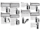
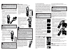
1. Set the Rotary
Dial to
posi-
tion.
2. Connect the red
test lead to the
V terminal and
the black test lead
to the COM termi-
nal.
3. Connect the red
test lead to the
positive (+) side
and black test
leads to the nega-
tive (-) side of the circuit under test. The reading
is displayed. A reversed connection is indicated
as a negative value.
DANGER To avoid electrical shock:
Never make measurement on a circuit in
which voltage over 1000V exists.
Keep fi ngers away from jaws during mea-
surements.
Resistance/Continuity/Capacitance
Measurements
DANGER To reduce the risk of
electric shock for Resistance, Continuity, and
Capacitance measurements, never use the
meter on an energized circuit. Make sure a
capacitor is fully discharged before touching
or attempting to make a measurement.
Resistance
1. Set the Rotary Dial to
position.
2. Connect the red test lead
to the V terminal and the
black test lead to the COM
terminal.
Confi rm “OL” is indicated on
the display, and then short-
circuit the tips of test leads
to make the indication zero.
3. Connect the test leads to
the both ends of the resistor
under test.
4. The reading is displayed.
CAUTION After shorting the test leads,
the displayed value may not be zero due to the
resistance of test leads themselves.
Continuity
1. Set the Rotary Dial to
position.
2. Connect the red test lead
to the V terminal and the
black test lead to the COM
terminal.
Confi rm “OL” is indicated on
the display, and then short-
circuit the tips of test leads
to make the indication zero.
A buzzer will sound.
3. Connect the test leads to the
both ends of the conductor
under test. If the resistance under test is 30
or less, the buzzer will sound.
Capacitance
1. Set the Rotary Dial to
position.
2. Connect the red test lead
to the V terminal and the
black test lead to the COM
terminal.
3. Discharge capacitor.
4. Connect the test leads to the
both ends of the capacitor
under test.
5. The reading is displayed.
DANGER To avoid electrical shock:
Never make measurement on a circuit in
which voltage over 1000V exists.
12V
G
T
O
R
E
E
E
C
T
D
T
L
A
O
V
V
T
L
A
O
R
D
O
E
T
C
T
E
G
E
L
O
V
D
R
E
T
E
O
T
C
G
E
T
A
V
R
O
E
T
C
T
E
D
T
L
A
O
G
E
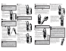
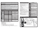
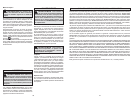
DC Current (Cat. No. 2238-20 only)
Temperature
(Cat. No. 2238-20 only)
1. Set the Rotary Dial to
position.
2. Connect the K-type Tem-
perature Probe to the input
terminal. The positive (+)
side of Probe should be
connected to V.
3. Place the probe sensor in
the desired location.
4. The reading is displayed.
WARNING Never connect the
Temperature Probe to an energized circuit.
CAUTION When the Rotary Dial is set
to , OL should be displayed. If anything else is
displayed, something may be wrong with the
meter. Stop using the meter immediately.
Hz Frequency (Cat. No. 2239-20 only)
1.Set the Dial to Hz position.
2. Voltage: Connect the red
test lead to the V termi-
nal and the black test lead
to the COM terminal.
Connect the test leads to
the circuit under test. The
reading is displayed.
Current: Press the jaw open-
ing trigger to open the jaws
and clamp them onto the
conductor under test. The
reading is displayed.
NOTE: Do not clamp over 2
or more wires at the same
time. Irregular results will
occur.
T
A
E
G
D
E
O
T
C
T
E
R
O
V
L
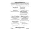
probe
Module
Control
Flame
sensor
V
O
D
E
T
C
T
R
O
E
G
E
A
T
L
V
O
R
D
E
T
C
T
E
O
E
A
G
L
T
V
O
R
D
E
T
C
T
E
O
E
A
G
L
T
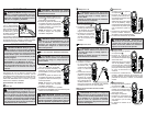
DANGER The LED may not be
displayed due to installation condition of
electrical circuit or equipment. Never touch
the circuit under test to avoid possible danger
even if the LED for NCVD is not displayed.
Check the functionality of LED on a well-
known power supply prior to measurement.
When the LED doesn’t light up, do not make
measurement.
NCVD indication is affected by external volt-
age, and how the meter is held or placed.
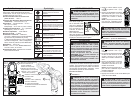
When the meter is on in any
function, the non-contact volt-
age detector will indicate with a
Red LED on the display when
an electric fi eld exceeding 90V is
detected. Place the edge of the
jaw labeled “Voltage Detector”
near the electric fi eld.
Non-Contact Voltage Detection (NCVD)
T
E
T
O
C
R
T
A
D
E
G
E
O
V
L
1. Set the Rotary Dial to
position.
2. Connect the red test lead
to the V terminal and the
black test lead to the COM
terminal.
3. Connect the test leads to
the circuit under test. The
reading is displayed.
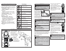
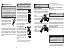
DC Voltage
DANGER To avoid electrical shock:
Never make measurement on a circuit in
which voltage over 1000V exists.
Keep fi ngers away from jaws during mea-
surements.
AC Voltage
V
T
O
R
G
E
D
E
E
C
T
A
O
T
L
1. Set the Rotary Dial to
position. DC mark is
displayed.
2. Connect the red test lead to the V terminal and
the black test lead to the COM terminal. Contact
the red test lead to the fl ame sensor probe and
the black test lead to the control module.
3. Turn on the heating unit. The reading is dis-
played.