


4
5
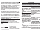
Cat. No. Volts DC No Load RPM Blade Size Arbor Depth of Cut At 90° Depth of Cut at 45°
2731-20 18 5000 7-1/4" 5/8" 0 to 2-1/2" 0 to 1-13/16"
FUNCTIONAL DESCRIPTION
SYMBOLOGY
SPECIFICATIONS
ASSEMBLY
WARNING Recharge only with the
charger specifi ed for the battery. For specifi c
charging instructions, read the operator’s
manual supplied with your charger and bat-
tery.
Inserting/Removing the Battery
To remove the battery, push in the release buttons
and pull the battery pack away from the tool.
To insert the battery, slide the pack into the body of
the tool. Make sure it latches securely into place.
Selecting Blade
Select a blade appropriate for your application.
Refer to the “Accessories” section for a list of blades
to be used for the proper applications of this tool.
Always use sharp blades. Dull blades tend to
overload the tool and increase the chance of KICK-
BACK. Only use thin kerf blades with a maximum
safe operating speed greater than the no load RPM
marked on the tool’s nameplate. Read the blade
manufacturer’s instructions before use. Do not use
any type of abrasive cut-off wheel or dry diamond
cutting blades. Use the correct blade type for your
application. Using the wrong blade may result in
reduced performance or damage to the blade. Do
not use blades that are cracked or have broken
teeth. Do not sharpen ferrous metal cutting blades;
see the blade manufacturer’s recommendations
regarding sharpening.
Checking the Operation of the Lower Guard
Check the operation and condition of the lower
guard lever. If the guard and the lever are not op-
erating properly, they must be serviced before use.
Lower guard may operate sluggishly due to dam-
aged parts, gummy deposits, or a buildup of debris.
1. Remove battery pack before checking the lower
guard.
2. Place the tool on its side.
NOTE: This procedure will not show proper lower
guard operation if the tool is not on its side.
3. Grasp the lower guard by the sides and push it
all the way back into the blade housing.
4. Release the lower guard.
• If the guard immediately springs back into place,
it is working correctly and you may continue with
use.
• If the guard does not immediate spring back
into place, clean the upper and lower guards
to remove all chips and debris. Then, check
the operation again by starting with step 1.
• If the guard still does not immediately spring
back into place, contact a MILWAUKEE service
facility for repairs.
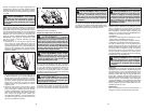
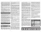
3. Raise or lower the shoe to the desired position.
Markings in 1/4" increments are located on the
inner side of the upper guard for depth setting.
For the proper depth setting, the blade should
extend no more than 1/8" to 1/4" below the mate-
rial being cut (Fig. 3).
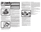
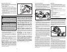
Installing and Removing Blades
1. Remove battery pack before installing or
removing blades.
2. Place the saw on a fl at surface with the blade fac-
ing upwards. To remove the bolt from the spindle,
push in the spindle lock button. While holding in
the spindle lock button, use the wrench provided
with the tool to turn the bolt counterclockwise.
Remove the bolt and blade fl ange.
3. Slide the lower guard lever up to raise the lower
guard. Remove the blade from the spindle. Al-
ways clean the spindle, upper guard and lower
guard to remove any dirt and sawdust.
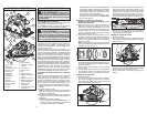
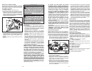
NOTE: Do not remove inner blade fl ange. Larger
diameter of inner fl ange (Fig. 1) should face the
blade.
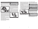
Fig. 2
WARNING Always remove battery
pack before changing or removing acces-
sories. Only use accessories specifically
recommended for this tool. Others may be
hazardous.
4. To install a blade, place the blade on the spindle
with the teeth pointing in the same direction as
the arrow on the lower guard. Release the lower
guard lever.
5. Place the blade fl ange on the spindle and hand
tighten the bolt.
6. While holding in the spindle lock button, use the
wrench to turn the bolt clockwise and tighten.
Adjusting Depth
1. Remove battery pack.
2. To adjust the depth of the cut, hold the saw by
the handle and loosen the depth adjusting lever
by pushing it down toward the shoe (Fig. 2).
Volts
Direct Current
No Load Revolutions per Minute
(RPM)
C
US
Underwriters Laboratories, Inc.
United States and Canada
Bolt
Outer fl ange
Inner fl ange
Spindle
Fig. 1
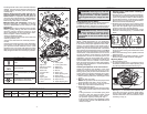
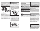
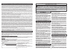
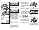
1. Sight lines
2. Spindle lock button
3. Front handle
4. Rafter hook
5. Lock-off button
6. Trigger
7. Handle
8. Upper guard
9. Lower guard lever
10. Shoe
17
16
19
20
18
21
1
2
5
3
6
7
4
12
8
14
9
13
10
11
15
11. Lower guard
12. Lower guard arrow
13. Blade bolt
14. Blade fl ange
15. Wrench
16. Bevel scale
17. Bevel adjusting knob
18. Bevel pointer
19. Rip fence adjusting knob
20. Rip fence slot
21. Depth adjusting lever
retracting handle and as soon as blade enters the
material, the lower guard must be released. For
all other sawing, the lower guard should operate
automatically.
• Always observe that the lower guard is cov-
ering the blade before placing saw down on
bench or fl oor. An unprotected, coasting blade will
cause the saw to walk backwards, cutting whatever
is in its path. Be aware of the time it takes for the
blade to stop after switch is released.
• Maintain labels and nameplates. These carry
important information. If unreadable or missing,
contact a MILWAUKEE service facility for a free
replacement.
• WARNING Some dust created by power sanding,
sawing, grinding, drilling, and other construction
activities contains chemicals known to cause
cancer, birth defects or other reproductive harm.
Some examples of these chemicals are:
• lead from lead-based paint
• crystalline silica from bricks and cement and other
masonry products, and
• arsenic and chromium from chemically-treated
lumber.
Your risk from these exposures varies, depending
on how often you do this type of work. To reduce
your exposure to these chemicals: work in a well
ventilated area, and work with approved safety
equipment, such as those dust masks that are spe-
cially designed to fi lter out microscopic particles.