


6
7
1
2
3
4
5
6
0
10
30
45
50
60
70
80
40
20
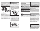
WARNING To reduce the risk of injury,
keep hands away from the blade and other
moving parts. Always wear safety goggles or
glasses with side shields. Use only specifi -
cally recommended accessories. Others may
be hazardous.
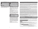
2. Line up the sight line with your cutting line. Posi-
tion your arms and body to resist KICKBACK.
3. To start the saw, push the lock-off button down
while pulling the trigger. Allow the motor to reach
full speed before beginning cut.
4. While cutting, keep the shoe fl at against the
workpiece and maintain a fi rm grip. Do not force
the saw through the workpiece. Forcing a saw
can cause KICKBACK.
5. If making a partial cut, restarting in mid-cut or
correcting direction, allow the blade to come to
a complete stop. To resume cutting, center the
blade in the kerf, back the saw away from cut-
ting edge a few inches, push the lock-off button
down while pulling the trigger and re-enter the
cut slowly.
6. If the saw binds and stalls, maintain a fi rm grip
and release the trigger immediately. Hold the
saw motionless in the workpiece until the blade
comes to a complete stop.
7. After fi nishing a cut, be sure the lower guard
closes and the blade comes to a complete stop
before setting the saw down.
OPERATION
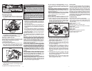
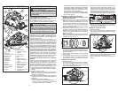
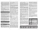
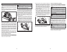
Bevel adjustment
screw
Fig. 5
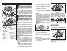
Kickback causes and related warnings
– Kickback is a sudden reaction to a pinched,
bound or misaligned saw blade, causing an un-
controlled saw to lift up and out of the workpiece
toward the operator;
– When the blade is pinched or bound tightly by the
kerf closing down, the blade stalls and the motor
reaction drives the unit rapidly back toward the
operator;
– If the blade becomes twisted or misaligned in
the cut, the teeth at the back edge of the blade
can dig into the top surface of the wood causing
the blade to climb out of the kerf and jump back
toward the operator.
Kickback is the result of saw misuse and/or incor-
rect operating procedures or conditions and can
be avoided by taking proper precautions as given
below:
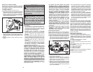
• Maintain a fi rm grip with both hands on the
saw and position your arms to resist kickback
forces. Position your body to either side of the
blade, but not in line with the blade. Kickback
could cause the saw to jump backwards, but kick-
back forces can be controlled by the operator, if
proper precautions are taken.
• When blade is binding, or when interrupting
a cut for any reason, release the trigger and
hold the saw motionless in the material until
the blade comes to a complete stop. Never at-
tempt to remove the saw from the work or pull
the saw backward while the blade is in motion
or kickback may occur. Investigate and take
corrective actions to eliminate the cause of blade
binding.
• When restarting a saw in the workpiece, centre
the saw blade in the kerf and check that saw
teeth are not engaged into the material. If saw
blade is binding, it may walk up or kickback from
the workpiece as the saw is restarted.
• Support large panels to minimise the risk of
blade pinching and kickback. Large panels tend
to sag under their own weight. Supports must be
placed under the panel on both sides, near the line
of cut and near the edge of the panel.
Fig. 4
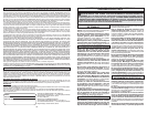
3. Hold the front of the shoe and rotate the saw by
the handle to the desired angle as indicated by
the markings on the bevel scale.
4. Tighten the bevel adjusting knob securely.
Adjusting the Blade to Shoe
The shoe has been adjusted at the factory to a 90
degree setting. Inspect the saw regularly to make
sure the blade is 90 degrees to the shoe.
1. Remove battery pack.
2. Set the bevel pointer to zero.
3. To make sure the blade is 90 degrees to the
shoe, place saw on the blade side and retract
lower guard. Place a square against the blade
and shoe to inspect the degree setting (Fig. 5).
WARNING Always remove battery pack
before changing or removing accessories.
Only use accessories specifi cally recommend-
ed for this tool. Others may be hazardous.
Electric Brake
The electric brake engages when the trigger is
released, causing the blade to stop and allowing
you to proceed with your work. Generally, the saw
blade stops within two seconds. However, there
may be a delay between the time you release the
trigger and when the brake engages. Occasionally
the brake may miss completely. If the brake misses
frequently, the saw needs servicing by an autho-
rized MILWAUKEE service facility. The brake is not
a substitute for the guard, and you must always wait
for the blade to stop completely before removing
the saw from the workpiece.
Troubleshooting
If the blade does not follow a straight line:
• Teeth are dull. This is caused by hitting a hard
object such as a nail or stone, dulling teeth on one
side. The blade tends to cut to the side with the
sharpest teeth.
• Shoe is out of line or bent
• Blade is bent
• Rip fence or guide is not being used
If the blade binds, smokes or turns blue from friction:
• Blade is dull
• Blade is on backwards
• Blade is bent
• Blade is dirty
• Workpiece is not properly supported
• Incorrect blade is being used
• Battery charge is low
• Do not use dull or damaged blades. Unsharp-
ened or improperly set blades produce narrow
kerf causing excessive friction, blade binding and
kickback.
• Blade depth and bevel adjusting locking levers
must be tight and secure before making cut. If
blade adjustment shifts while cutting, it may cause
binding and kickback.
• Use extra caution when sawing into existing
walls or other blind areas. The protruding blade
may cut objects that can cause kickback.
General Operation
Always clamp the workpiece securely on a saw
horse or bench. See “APPLICATIONS” for the cor-
rect way to support your work in different situations.
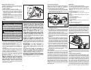
1. Draw a cutting line. Place the front of the shoe on
the edge of the workpiece without making blade
contact. Hold the handle with one hand and the
front handle with the other (Fig. 6).
4. To adjust the degree setting, loosen the bevel
adjusting knob. Turn the bevel adjustment screw
in or out until the blade is at a 90 degree angle
with the shoe.
5. Tighten the bevel adjusting knob securely.
Fig. 6
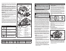
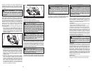
1/4” 6mm
Fig. 3
4. Lift the depth adjusting lever up towards the
motor housing to secure the shoe position.
Adjusting Bevel Angle
1. Remove battery pack.
2. To adjust the angle of the cut, hold the saw by
the handle and loosen the bevel adjusting knob
(Fig. 4).