page 10
Water
Shut-Off
Valve
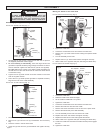
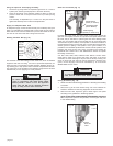
Fig. 18
Gear
Shift
Lever
To reduce the risk of injury, always check the
work area for hidden wires before coring.
Coring Procedure (Fig. 18)
1. Select and install a bit following guidelines in "Selecting and Installing
a Core Bit".
2. Secure the rig to the work surface using one of the methods de-
scribed in "Methods for Securing Equipment to Work Surface".
3. With the motor OFF, adjust the gear to either high or low speed
according to the guidelines in "Selecting Speeds".
NOTE: DO NOT SHIFT SPEEDS WHEN THE DYMODRILL MOTOR IS
ON. To adjust the speed on all Dymodrills, move the gear shift lever
to the desired setting.
WARNING!
20 Amp
Operating
Range
15 Amp
Operating
Range
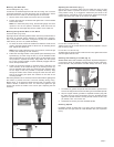
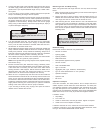
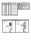
Fig. 16
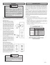
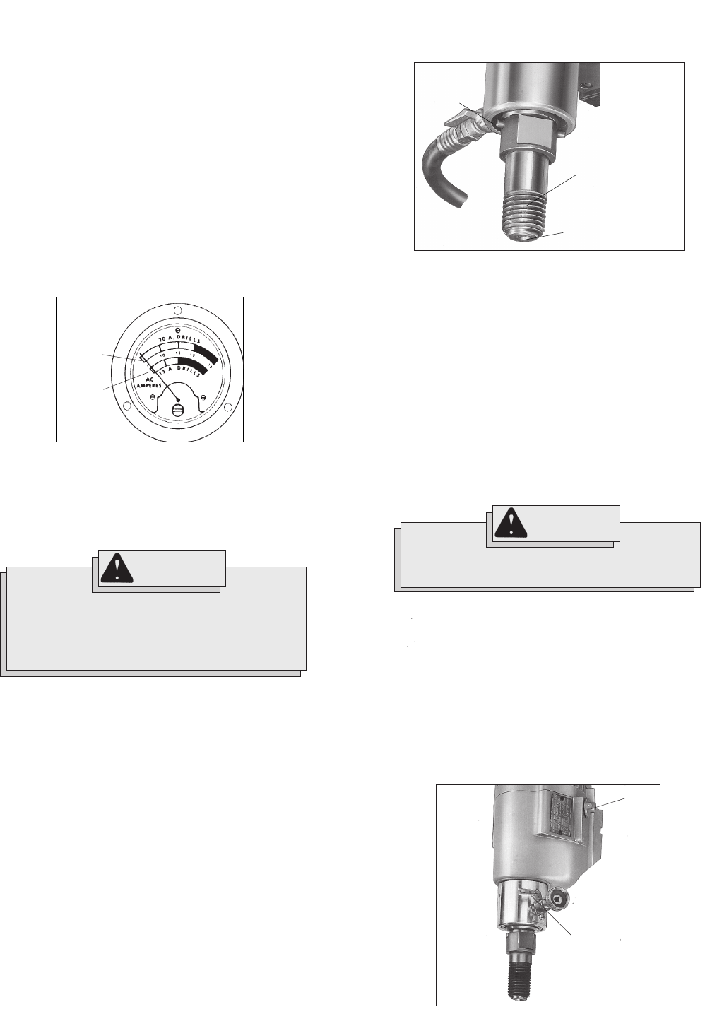
Reading the Meter Box (Fig. 16)
The ammeter is the dial indicator on the meter box, which is standard
equipment with the Vac-U-Rig
®
and can be purchased separately for
other Dymorigs. The ammeter provides pressure feedback during cor-
ing, allowing you to help prevent motor overload and premature bit wear.
The green area on the ammeter is the operating range and the red area
indicates that you are applying too much pressure.
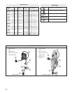
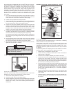
Dymodrill Nos. 4079, 4090, and 4094 contain a shear pin to protect the
gear and motor against overload. This pin drives the spindle sleeve. If the
bit binds, the pin will shear to prevent gear and motor damage. Extra
shear pins are supplied with each Dymodrill and can be replaced (see
"Accessories" for part numbers). It is important to check the condition of
the spindle before using the tool each time. The spindle must be smooth
without grooves or pitting. If the spindle is not in good condition, it is
possible for the threaded spindle sleeve and the internal spindle to weld
together and seize during coring (see "Lubricating the Spindle for
Dymodrills with a Shear Pin" in the "Maintenance" section for spindle
lubricating instructions).
Cat. Nos. 4004, 4005, 4092, 4096 and 4097 feature a friction clutch
rather than a shear pin to protect the motor and gears. If the motor
overloads, the clutch will begin to slip and the bit will stop rotating. The
clutch is factory-set and does not require adjustment. Nuisance (fre-
quent) clutch slippage should be addressed by an authorized
MILWAUKEE service center.
Supply an Adequate Water Flow
An adequate supply of water must flow freely and constantly during the
entire cut. Dymodrills are equipped with a built-in water shut-off valve to
allow water to flow down the inside and up around the outside of the bit.
This acts to cool the bit and flush cuttings from the hole.
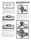
Using the Optional Telescoping Assembly
1. Secure the rig using either an expansion-type anchor or a vacuum
system (see "Securing the Equipment to the Work Surface").
2. Place the top flange of the extension against a ceiling or wall and
place the other end on the jack screw at the top of the Dymorig
column.
The assembly is adjustable up to 14 feet. Turn the jack screw to
tighten the assembly and to make small adjustments.
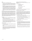
Fig. 17
Spindle Sleeve
(Shear pin models)
Threaded Spindle
(Clutch Models)
Shear Pin
Retaining Ring
(shear pin model only)
Shear Pin and Clutch (Fig. 17)
WARNING!
To reduce the risk of injury, always use Dymo-
drills in conjunction with meter boxes. Meter
Boxes provide a switch to turn the Dymodrill
motor OFF and ON and an optimum operation
range to help prevent motor overload.


