


4 5
2
3
4
1
6
7
8
5
10
11
12
9
13
14
15
16
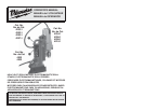
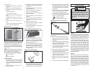
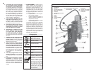
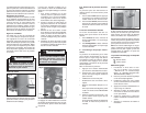
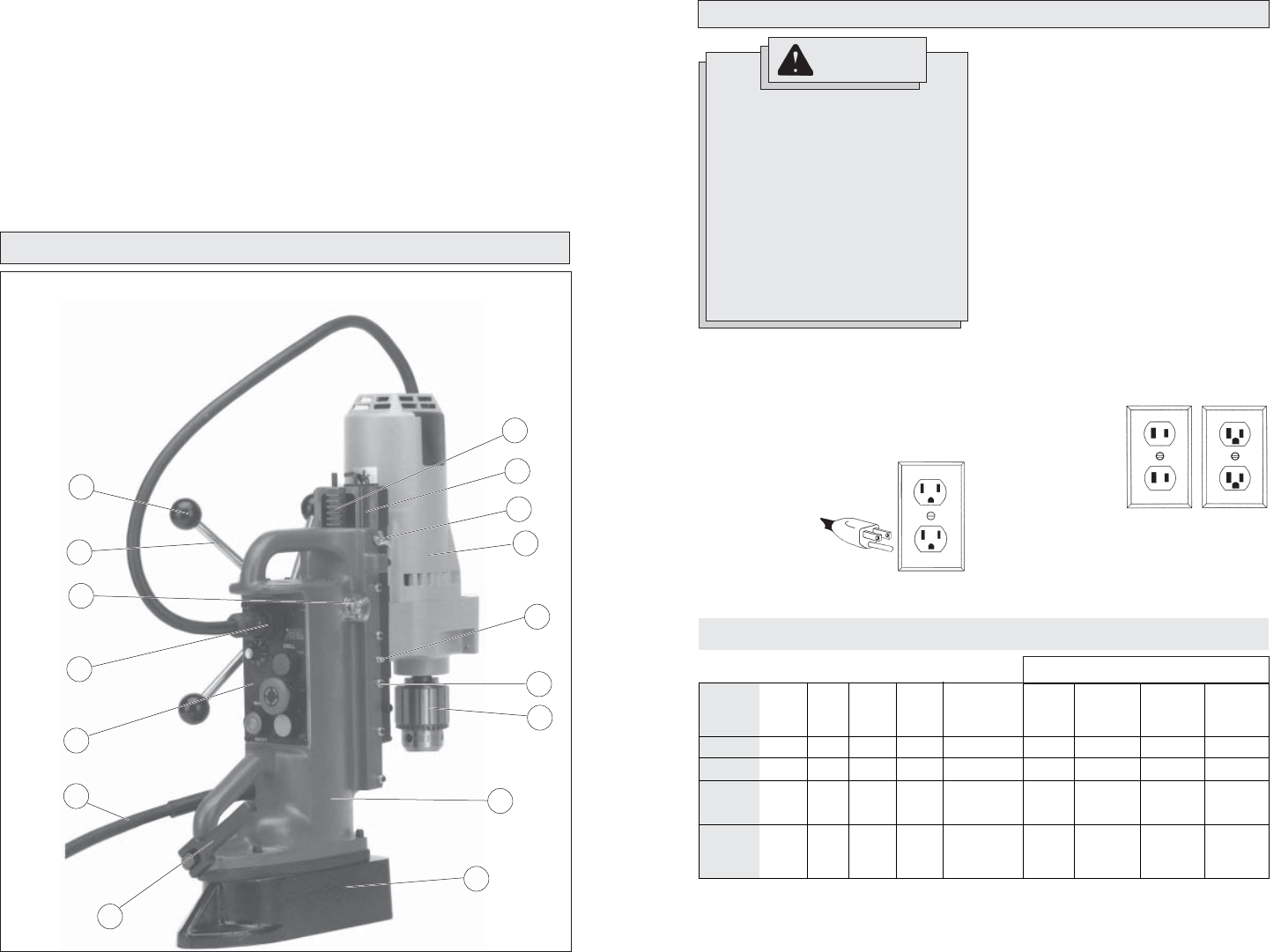
FUNCTIONAL DESCRIPTION
11. WARNING: Some dust created by
power sanding, sawing, grinding, drill-
ing, and other construction activities
contains chemicals known to cause
cancer, birth defects or other reproduc-
tive harm. Some examples of these
chemicals are:
• lead from lead-based paint
• crystalline silica from bricks and ce-
ment and other masonry products,
and
1. Rack
2. Slide
3. Slide locking wing screw
4. Drill motor
5. Grease fi tting
6. Gib adjusting screws
7. Chuck
8. Housing
9. Magnet
10. Adjusting handle
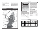
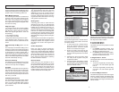
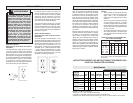
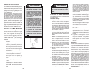
M.T. - Internal Morse Taper Socket
• - 5/8" -11 or 1/2" -13 taps not recommended
**- Requires use of 3/4" shank arbor, Cat. No. 49-57-0030
* - Requires use of #3 MT Arbor, Cat. No. 49-57-0010 or 49-57-0014
Chuck
or Taper
1/2" Chuck
3/4" Chuck
No. 3 M.T.
-
No. 3 M.T.
-
Steel
Hawg™
Cutters
-
4" **
2" *
4" *
3" *
5" *
Amps
6.2
11.5
11.5
-
11.5
-
No
Load
RPM
600
350
750
375
500
250
Drill
5/8"
1-3/8"
3/4"
1-1/4"
1-1/8"
1-1/2"
Coarse
Thread
Tap
3/8" - 16
7/8" - 9
-
7/8" - 9
-
1" - 8
Volts
AC
120
120
120
-
120
-
Speed
--
--
HIGH
LOW
HIGH
LOW
Drill
Motor
Cat. No.
4253-1 •
4262-1
4292-1
-
4297-1
-
Fine
Thread
Tap
5/8" - 18
1" - 14
-
1" - 14
-
1" - 14
Specifi cations
Maximum Recommended Capacity
11. Cord
12. Control panel
13. Control panel socket
14. Wing screw assembly
15. Feed handle
16. Feed handle grip
• arsenic and chromium from chemically-
treated lumber.
Your risk from these exposures varies,
depending on how often you do this
type of work. To reduce your exposure
to these chemicals: work in a well ven-
tilated area, and work with approved
safety equipment, such as those dust
masks that are specially designed to
fi lter out microscopic particles.
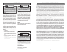
The grounding prong in the plug is connected
through the green wire inside the cord to
the grounding system in the tool. The green
wire in the cord must be the only wire con-
nected to the tool's grounding system and
must never be attached to an electrically
“live” terminal.
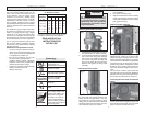
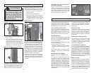
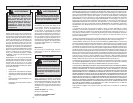
Your tool must be plugged into an appropri-
ate outlet, properly installed and grounded in
accordance with all codes and ordinances.
The plug and outlet should look like those
in Figure A.
Double Insulated Tools:
Tools with Two Prong Plugs
Tools marked “Double Insulated” do not
require grounding. They have a special
double insulation system which satisfies
OSHA requirements and complies with the
applicable standards of Underwriters Labora-
tories, Inc., the Canadian Standard Associa-
tion and the National
Electrical Code.
Double Insulated
tools may be used
in either of the 120
volt outlets shown in
Figures B and C.
Grounded Tools:
Tools with Three Prong Plugs
Tools marked “Grounding Required” have a
three wire cord and three prong grounding
plug. The plug must be connected to a prop-
erly grounded outlet (See Figure A). If the
tool should electrically malfunction or break
down, grounding
provides a low re-
sistance path to
carry electricity
away from the user,
reducing the risk of
electric shock.
Fig. B
Fig. C
Fig. A
Improperly connecting the grounding
wire can result in the risk of electric
shock. Check with a qualifi ed electri-
cian if you are in doubt as to whether
the outlet is properly grounded. Do
not modify the plug provided with
the tool. Never remove the grounding
prong from the plug. Do not use the
tool if the cord or plug is damaged.
If damaged, have it repaired by a
MILWAUKEE service facility before
use. If the plug will not fi t the outlet,
have a proper outlet installed by a
qualifi ed electrician.
GROUNDING
WARNING