


4
5
The grounding prong in the plug is connected
through the green wire inside the cord to the
grounding system in the tool. The green wire in the
cord must be the only wire connected to the tool's
grounding system and must never be attached to
an electrically “live” terminal.
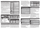
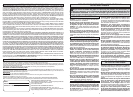
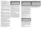
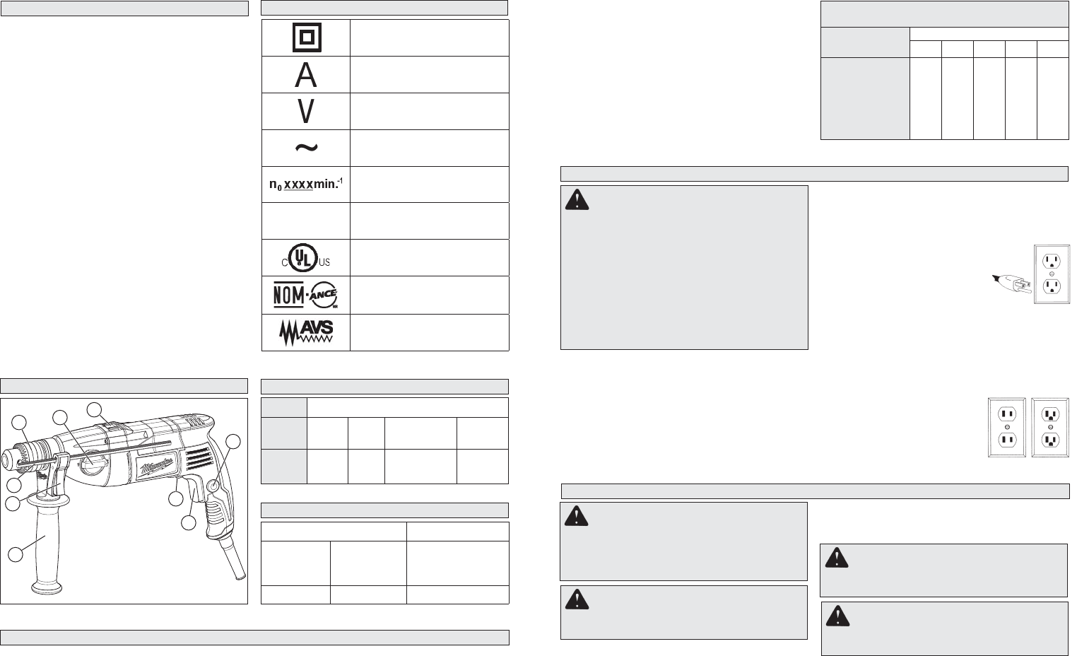
Your tool must be plugged into
an appropriate outlet, properly
installed and grounded in accord-
ance with all codes and ordinances.
The plug and outlet should look like
those in Figure A.
Double Insulated Tools:
Tools with Two Prong Plugs
Tools marked “Double Insulated” do not require
grounding. They have a special double insula-
tion system which satisfi es OSHA requirements
and complies with the applicable standards of
Underwriters Laboratories, Inc.,
the Canadian Standard Asso-
ciation and the National Elec-
trical Code. Double Insulated
tools may be used in either of
the 120 volt outlets shown in
Figures B and C.
Grounded Tools: Tools with Three Prong Plugs
Tools marked “Grounding Required” have a three
wire cord and three prong grounding plug. The
plug must be connected to a properly grounded
outlet (See Figure A). If the tool should electrically
malfunction or break down, grounding provides a
low resistance path to carry electricity away from
the user, reducing the risk of electric shock.
SPECIFIC SAFETY RULES
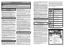
SPECIFICATIONS
Tool
Cat. No.
Volts
AC
Amps
No Load
RPM
No Load
BPM
5380-21 120 9 Low 0 - 1500
High 0 - 3500
24,000
56,000
• Wear ear protectors when impact drilling.
Exposure to noise can cause hearing loss.
• Use auxiliary handle(s), if supplied with the
tool. Loss of control can cause personal injury.
• Hold power tool by insulated gripping surfaces,
when performing an operation where the cutting
accessory may contact hidden wiring or its own
cord. Cutting accessory contacting a “live” wire
may make exposed metal parts of the power tool
“live” and could give the operator an electric shock.
• Maintain labels and nameplates. These carry
important information. If unreadable or missing,
contact a MILWAUKEE service facility for a free
replacement.
• WARNING: Some dust created by power sanding,
sawing, grinding, drilling, and other construction
activities contains chemicals known to cause
cancer, birth defects or other reproductive harm.
Some examples of these chemicals are:
• lead from lead-based paint
• crystalline silica from bricks and cement and
other masonry products, and
• arsenic and chromium from chemically-treated
lumber.
Your risk from these exposures varies, depending
on how often you do this type of work. To reduce
your exposure to these chemicals: work in a well
ventilated area, and work with approved safety
equipment, such as those dust masks that are spe-
cially designed to fi lter out microscopic particles.
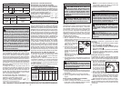
FUNCTIONAL DESCRIPTION
Double Insulated
Amps
Volts
Alternating Current Only
No Load Revolutions per
Minute (RPM)
BPM
Blows per Minute (BPM)
Underwriters Laboratories,
Inc.
United States and Canada
Mexican Approvals Marking
Anti-Vibration System
SYMBOLOGY
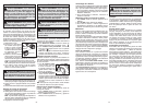
2
1
3
5
4
6
8
7
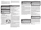
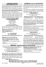
1. Side handle
2. Clamping lever
3. Depth gauge
4. Chuck
5. Speed selector
6. Hammer/Drill lever
7. Lock button
8. Trigger
9. Forward/Reverse lever
9
Fig. B
Fig. C
Fig. A
GROUNDING
WARNING Improperly connecting the
grounding wire can result in the risk of elec-
tric shock. Check with a qualifi ed electrician
if you are in doubt as to whether the outlet is
properly grounded. Do not modify the plug
provided with the tool. Never remove the
grounding prong from the plug. Do not use
the tool if the cord or plug is damaged. If
damaged, have it repaired by a MILWAUKEE
service facility before use. If the plug will not
fi t the outlet, have a proper outlet installed by
a qualifi ed electrician.
Grounded tools require a three wire extension
cord. Double insulated tools can use either a two
or three wire extension cord. As the distance from
the supply outlet increases, you must use a heavier
gauge extension cord. Using extension cords with
inadequately sized wire causes a serious drop in
voltage, resulting in loss of power and possible tool
damage. Refer to the table shown to determine the
required minimum wire size.
READ AND SAVE ALL
INSTRUCTIONS FOR FUTURE USE.
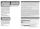
* Based on limiting the line voltage drop to fi ve volts at
150% of the rated amperes.
EXTENSION CORDS
Recommended Minimum Wire Gauge
For Extension Cords*
Nameplate
Amperes
Extension Cord Length
25' 50' 75' 100' 150'
0 - 2.0
2.1 - 3.4
3.5 - 5.0
5.1 - 7.0
7.1 - 12.0
12.1 - 16.0
16.1 - 20.0
18
18
18
18
16
14
12
18
18
18
16
14
12
10
18
18
16
14
12
10
--
18
16
14
12
10
--
--
16
14
12
12
--
--
--
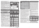
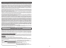
Drill Only Hammer-Drill
Twist Drill
Bit (Wood)
Twist Drill Bit
(Steel)
Carbide Tipped
Percussion Bit
(concrete)
1/2" 5/8" 3/4"
CAPACITIES
The smaller the gauge number of the wire, the
greater the capacity of the cord. For example, a 14
gauge cord can carry a higher current than a 16
gauge cord. When using more than one extension
cord to make up the total length, be sure each cord
contains at least the minimum wire size required.
If you are using one extension cord for more than
one tool, add the nameplate amperes and use the
sum to determine the required minimum wire size.
Guidelines for Using Extension Cords
• If you are using an extension cord outdoors, be
sure it is marked with the suffi x “W-A” (“W” in Cana-
da) to indicate that it is acceptable for outdoor use.
• Be sure your extension cord is properly wired
and in good electrical condition. Always replace a
damaged extension cord or have it repaired by a
qualifi ed person before using it.
• Protect your extension cords from sharp objects,
excessive heat and damp or wet areas.
ASSEMBLY
WARNING To reduce the risk of injury,
always unplug tool before changing or re-
moving accessories. Only use accessories
specifi cally recommended for this tool. Others
may be hazardous.
WARNING To reduce the risk of injury,
always use a side handle when using this tool.
Always brace or hold securely.
Adjusting the Side Handle Position
1. Loosen the side handle by unscrewing the side
handle grip until the side handle rotates freely.
2. Rotate the side handle to the desired position.
3. Tighten the side handle grip securely.
Setting the Depth Gauge
1. Press in the clamping lever.
2. Slide the depth gauge rod backward or forward
until it is set for the desired depth.
WARNING To reduce the risk of injury
do not grasp the bit while the chuck is rotat-
ing or while the bit is falling from the chuck.
WARNING To prevent personal injury,
always remove the chuck key from the chuck
after each use.
Installing Bits into Keyed Chucks
Be sure that the shank of the bit and the chuck
jaws are clean. Dirt particles may cause the bit
to line up improperly. Do not use bits larger than
the maximum recommended capacity of the drill
because gear damage or motor overloading may
result. For best performance, be sure that the bits
are properly sharpened before use.
NOTE: The drilling depth is the distance between
the tip of the bit and the tip of the rod.
3. Release the clamping lever.