


10 11
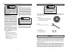
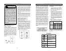
Adjusting the Depth of Cut
The tool depth can be adjusted by using
the depth adjustment knob or a 3/8" socket
wrench.
When using the depth adjustment knob, fully
open the locking lever and rotate knob to
the desired depth of cut. One revolution of
the depth adjustment knob is equal to 0.2".
For fine adjustments less than 5/32", use
the independent scale on the depth ad-
justment knob.
For deeper cuts:
1. Align the "0" on the scale with the ar-
row on the tool.
2. Rotate depth adjustment knob clock-
wise to desired depth measurement.
For shallower cuts:
1. Align the desired depth measurement
with the arrow on the tool.
2. Rotate depth adjustment knob coun-
terclockwise to "0."
Push-in locking lever to fully closed posi-
tion when finished adjusting.
OPERATION
WARNING!
Unplug the tool before changing
accessories or making adjust-
ments.
Never make adjustments while
the router is running.
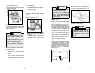
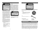
Holding the Tool
For Body Grip Base (Fig. 12):
You can hold this tool using the body grip
and handle or both handles. The body grip
features an adjustable strap, which can
be attached in two different positions for
maximum control and comfort.
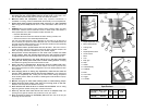
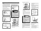
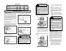
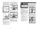
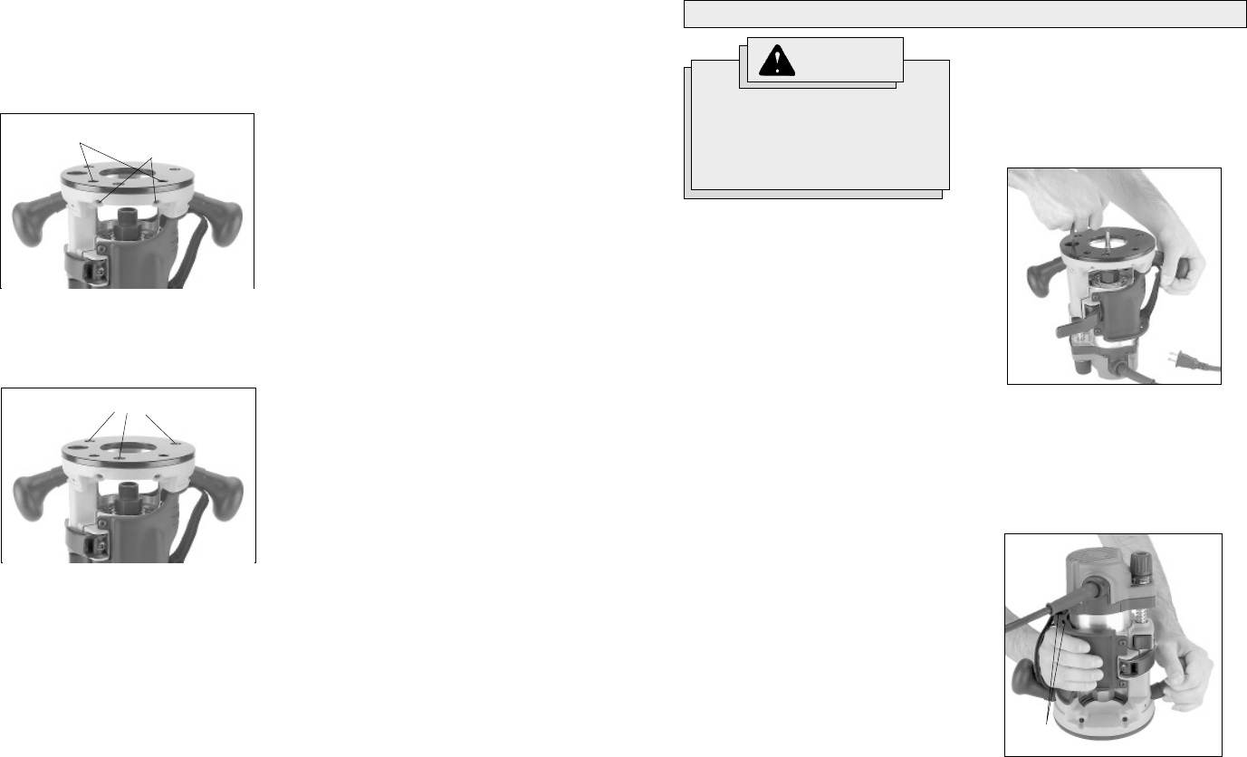
Installing/Removing Edge Guide
(Fig. 9)
To install an edge guide, loosen the two
rod screws. Insert the edge guide rods
into the rod holes and tighten the rod
screws.
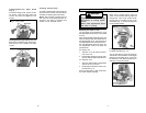
Installing Templet Guide
To install a templet guide, insert guide into
the center hole of router base and secure
according to templet guide instructions.
NOTE: The sub-base provided with this
tool does not accept templet guides. An
accessory sub-base is avaivable that
accepts 1-3/16" threaded inserts.
Installing/Removing Sub-base (Fig. 10)
Remove the sub-base screws. Place a sub-
base onto the tool. Replace sub-base
screws.
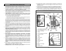
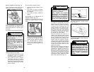
When using a socket wrench, place the
router on a flat surface and fully open the
locking lever. Insert a 3/8" socket wrench
into the hole on the base and turn to de-
sired depth (Fig. 11). Push-in locking lever
to fully closed position.
Fig. 12
Alternate
strap positions
Fig. 9
Rod holes
Rod screws
Fig. 10
Sub-base screws
Fig. 11