


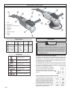
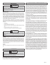
page 5
Grounded tools require a three wire extension cord. Double insulated tools
can use either a two or three wire extension cord. As the distance from the
supply outlet increases, you must use a heavier gauge extension cord. Us-
ing extension cords with inadequately sized wire causes a serious drop in
voltage, resulting in loss of power and possible tool damage. Refer to the
table shown to determine the required minimum wire size.
The smaller the gauge number of the wire, the greater the capacity of the
cord. For example, a 14 gauge cord can carry a higher current than a 16
gauge cord. When using more than one extension cord to make up the total
length, be sure each cord contains at least the minimum wire size required. If
you are using one extension cord for more than one tool, add the nameplate
amperes and use the sum to determine the required minimum wire size.
Guidelines for Using Extension Cords
• If you are using an extension cord outdoors, be sure it is marked with
the suffi x “W-A” (“W” in Canada) to indicate that it is acceptable for
outdoor use.
• Be sure your extension cord is properly wired and in good electrical
condition. Always replace a damaged extension cord or have it repaired
by a qualifi ed person before using it.
• Protect your extension cords from sharp objects, excessive heat and
damp or wet areas.
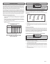
EXTENSION CORDS
Nameplate
Amperes
0 - 5
5.1 - 8
8.1 - 12
12.1 - 15
15.1 - 20
Extension Cord Length
25'
16
16
14
12
10
75'
16
14
12
10
10
100'
14
12
10
10
--
150'
12
10
--
--
--
200'
12
--
--
--
--
Recommended Minimum Wire Gauge
for Extension Cords*
* Based on limiting the line voltage drop to fi ve
volts at 150% of the rated amperes.
50'
16
16
14
12
10
READ AND SAVE ALL INSTRUCTIONS
FOR FUTURE USE.
TOOL ASSEMBLY
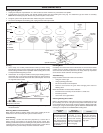
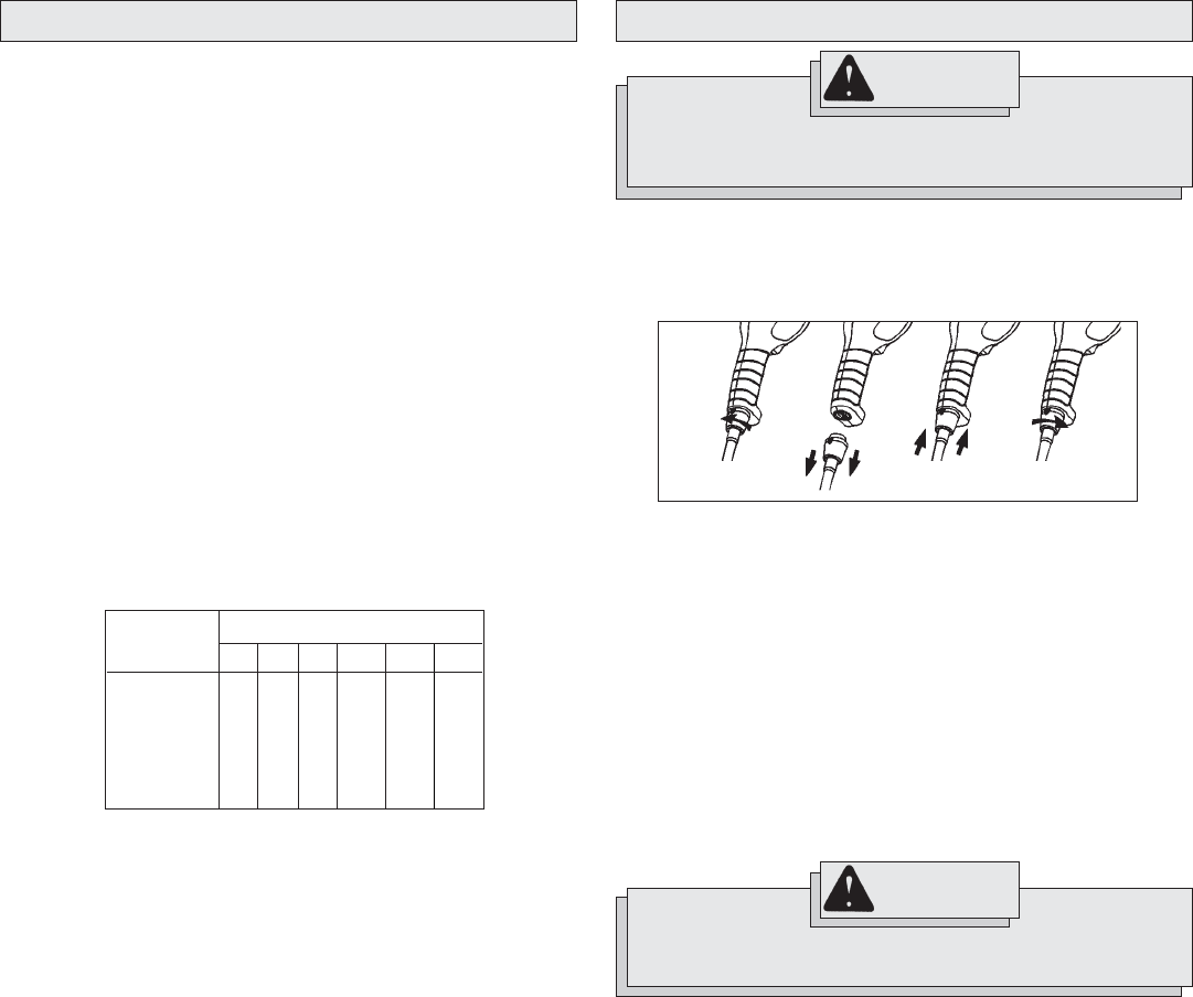
Removing and Replacing Quik-Lok
®
Cords (Select Models)
MILWAUKEE's exclusive Quik-Lok
®
Cords provide instant fi eld replacement
or substitution.
1. To remove the Quik-Lok
®
Cord, turn the cord nut 1/4 turn to the left and
pull it out.
2. To replace the Quik-Lok
®
Cord, align the connector keyways and push
the connector in as far as it will go. Turn the cord nut 1/4 turn to the
right to lock.
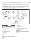
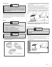
Installing the Side Handle
The side handle may be installed on either side of gear case for right or left
handed use. Position side handle in the location which offers best control and
guard protection. For operating zones that provide maximum protection for
the operator, see "Grinding". To install, thread side handle into side handle
socket on desired side of gear case and tighten securely.
Fig. 1
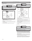
Installing, Adjusting, and Removing the Guard (Select Models)
The guard must be used when using the tool as a grinder. The guard should
be removed when using tool as a sander.
1. Unplug the tool and place it upside down on a level surface. Remove
any accessories from the spindle.
2. Place the grinding wheel guard over the spindle. Position the guard in
the location which offers best control and guard protection. For operating
zones that provide maximum protection for the operator, see "Grind-
ing".
3. Fasten the guard to the lower half of the gear case with screws and
lock washers provided.
To reduce the risk of injury when grinding, ALWAYS use the proper
guard. ALWAYS properly install the guard.
WARNING
WARNING
To reduce the risk of injury, always unplug tool before attaching
or removing accessories or making adjustments. Use only specifi -
cally recommended accessories. Others may be hazardous.