


8
OPERATION
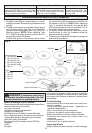
Press in the guard adjustment lock lever and ro-
tate the guard to one of the detent slots. The lock
lever must engage with one of the detents (Fig. 3).
2. To adjust the guard, press in the guard adjust-
ment lock lever and rotate the guard to one of
the detents (Fig. 3).
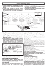
Position the guard in the location which offers
best control and guard protection. For operating
zones that provide maximum protection for the
operator, see Fig. 9.
3. To remove the guard, unplug tool and place it
upside down on a level surface. Remove any
accessories from spindle.
Press in the guard adjustment lock lever and
rotate the guard to line up the tabs with the slots
(Fig. 2). Then lift the guard straight up and away
from the tool.
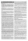
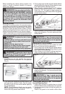
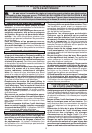
Starting and Stopping the Motor
1. To start the tool, pull the trigger.
2. To stop the tool, release the trigger.
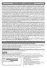
1. To lock the trigger on, hold the lock-on button in
while pulling the trigger. Release the trigger.
2. To unlock the trigger, pull the trigger and release.
The lock-on button will pop out.
Locking the Trigger
Select Models
The lock button holds the trigger in the ON position
for continuous use.
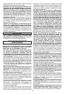
WARNING To reduce the risk of injury,
wear safety goggles or glasses with side shields.
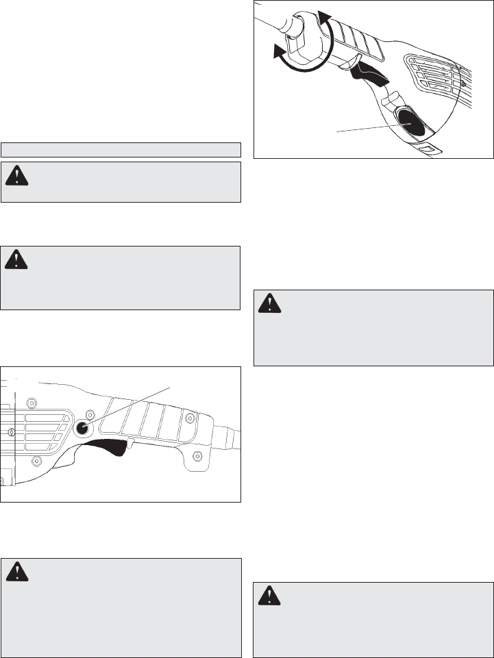
WARNING
To reduce the risk of injury
or damage to the tool, do not use the spindle
lock button to stop the spindle while the tool
is in use or is coasting after shut-off.
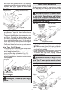
1. Unplug tool.
2. Press and hold the handle release button in
and rotate the rear handle to one of the nine
handle positions. The adjustable handle feature
has detents which allow the handle to snap into
position. Make sure the handle snaps fi rmly into
position and does not rotate.
Position the guard in the location which offers
best control and guard protection. For operating
zones that provide maximum protection for the
operator, see Fig. 9.
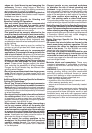
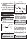
Adjusting the Rear Handle Position
Select Models
This tool is equipped with an adjustable rear handle.
This feature allows the user to adjust the angle of
the handle to nine positions for optimum operating
positions.
Handle releas button
(on bottom)
Fig. 5
WARNING
To reduce the risk of injury,
do not operate tool with handle release but-
ton pressed in or with handle not locked into
position. If the handle does not lock securely
into position, do not operate tool. Return the
tool to a MILWAUKEE service facility for repair
immediately.
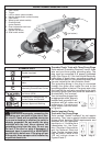
Sanding Disc and Grinding Wheel Selection
Use sanding discs and grinding wheels that are:
• correct size as written on tool's nameplate
• correct wheel type and grit for the job
• rated at or above the RPM listed in the “WARN-
ING” section on the tool's nameplate
Use backing pads, adapters, and other acces-
sories that are:
•correct size for tool and for sanding disc or grind-
ing wheel
•rated at or above the RPM listed in the “WARN-
ING” section on the tool's nameplate
•the proper accessory for the job
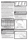
Sanding Disc and Grinding Wheel Material
Sanding discs and grinding wheels are made of
various materials and are designed for different
jobs. Be sure that you choose the proper sanding
disc or grinding wheel for the job you plan to do.
WARNING To reduce the risk of
personal injury and damage to the tool, use
ONLY accessories rated at or above the RPM
listed on the “WARNING” section of the tool's
nameplate.
WARNING To reduce the risk of injury,
always unplug tool before attaching or remov-
ing accessories or making adjustments. Use
only specifi cally recommended accessories.
Others may be hazardous.
Fig. 4
Lock-on button