


6 7
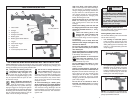
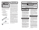
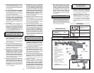
Plunger
Plunger rod
Tube holder
Barrel nut
Screw
Frame cap
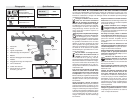
6562-21
Tube holder
Fig. 3
Installing 10oz Tube Holder Assembly (Cat. No. 6562-21) (Fig. 3)
1. Lock trigger or remove battery pack.
2. Press in and hold rod release trigger.
3. Grasp plunger rod handle and pull
plunger rod back until the rod tip is just
inside of tool.
4. Release rod release trigger.
5. The frame cap, barrel nut, and tube
holder are provided pre-assembled.
6. Thread barrel nut into the nose of the
tool. Tighten securely using the wrench
provided.
7. Press rod release trigger and push
plunger rod forward to access the tip of
the rod.
8. Attach plunger to the plunger rod, as
shown (Fig. 3). Tighten the screw se-
curely.
9. To remove tube holder, reverse proce-
dure.
ASSEMBLY
3. Insert the plunger rod from the rear of
the tool. It may be necessary to wiggle
the plunger rod slightly while pushing it
through the tool.
NOTE: Keep the plunger rod clean. Retract-
ing or inserting a plunger that is covered
with material may damage the internal parts
of the tool.
Inserting the Plunger Rod
Always lock the trigger or remove the battery
pack before inserting the plunger rod. Do not
run the tool to pull the plunger rod through
the tool, this will damage the tool and rod.
Manually push the plunger rod through the
tool, as follows:
1. Press in and hold rod release trigger.
2. Grasp the plunger rod handle. The teeth
on the plunger rod should point toward
the left and slightly down.
WARNING!
Always lock trigger or remove battery pack before changing or removing acces-
sories. Only use accessories specifi cally recommended for this tool. Others may
be hazardous.
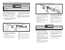
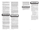
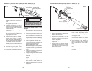
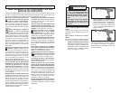
Washer (black)
Plunger
Plunger rod
Barrel nut
Washer (Steel)
6562-23
Screw
Tube holder
Fig. 4
1. Lock trigger or remove battery pack.
2. Press in and hold rod release trigger.
3. Grasp plunger rod handle and pull
plunger rod back until the rod tip is just
inside of tool.
4. Release rod release trigger.
5. Position washer (black) onto nose of
tool. The side with the larger collar fi ts
inside the tool.
6. Install tube holder over washer.
WARNING!
To reduce the risk of injury, keep hands out of the plunger area of the tool. Fingers
can be pinched between the tube holder and the plunger.
Installing Tube Holder Assembly (Cat. No. 6562-23) (Fig. 4)
7. Place washer (steel) between the tube
holder and barrel nut. Thread barrel nut
into nose of the tool. Tighten securely
using the wrench provided.
8. Press rod release trigger and push
plunger rod forward to access the tip of
the rod.
9. Attach plunger to the plunger rod, as
shown (Fig. 4). Tighten the screw se-
curely.
10. To remove tube holder, reverse proce-
Installing Caulk or Adhesive Tube
1. Lock trigger or remove battery pack.
2. Cut nozzle of tube at an angle and size
per manufacturer's recommendation to
suit the job. A smaller nozzle diameter
requires more force to push the caulk
and reduces battery life.
3. Break inner seal of tube using a long
nail or piece of wire. If the inner seal is
not broken, the caulk material may be
forced out the rear end of the tube and
damage the tool.
NOTE: Before using a partially fi lled
tube, remove any hardened material
with a long nail or piece of wire.
4. Press in and hold rod release trigger.
5. Grasp plunger rod handle and pull
plunger rod back to allow the caulk tube
to fi t inside carriage frame.
6. Insert caulk tube into carriage frame.
7. Push plunger rod handle forward until
the plunger is against the caulk tube.
8. Release rod release trigger.