


8 9
1. Lock trigger or remove battery pack.
2. Press in and hold rod release trigger.
3. Grasp plunger rod handle and pull
plunger rod back until the rod tip is just
inside of tool.
4. Release rod release trigger.
5. Position spacer and back cap (fine
threads) onto nose of the tool. The side
of the spacer with the double collar fi ts
inside the back cap.
6. Place backing washer on top of back cap
and thread barrel nut into nose of the
tool as shown. Tighten securely using
the wrench provided.
7. Press rod release trigger and push
plunger rod forward to access the tip of
the on rod.
8. Thread extenstion, plunger, barrel
plunger and nut onto the plunger rod in
the order shown. Tighten securely.
9. Thread barrel into back cap.
10. To remove barrel tube, reverse proce-
dure.
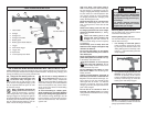
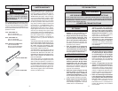
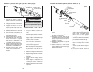
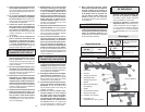
Installing Barrel Assembly (Cat. No. 6562-24) (Fig.5)
6562-24
Fig. 5
Barrel
Plunger rod
Plunger
Backing washer
Back cap
Spacer
Barrel plunger
Barrel nut
Nut
Nozzle cap
Nozzle
Double collar
Extension
Installing Sausage Type Pack
Always check sausage packs for punctures
or damage to the pack before installing. Do
not use a damaged or frozen pack.
1. Lock trigger or remove battery pack.
2. Press in and hold rod release trigger.
3. Grasp plunger rod handle and pull
plunger rod back to allow sausage pack
to fi t inside barrel tube.
4. Insert pack into barrel tube.
5. Cut off end of sausage pack.
NOTE: Before using a partially fi lled
pack, remove any hardened material.
6. Insert nozzle supplied with the sausage
pack into the nozzle cap (coarse thread).
Thread nozzle cap onto the front of bar-
rel tube (Fig. 5).
7. Cut nozzle at an angle and size per
manufacturer's recommendation to
suit the job. A smaller nozzle diameter
requires more force to push the caulk
and reduces battery life.
8. Press in and hold rod release trigger.
9. Push plunger rod handle forward until
plunger is against sausage pack.
10. Release rod release trigger.
OPERATION
Starting and Stopping and Controlling
Speed
1. Pull trigger to dispense material.
2. Increase or decrease pressure on the
trigger to dispense the material. Adjust
the speed dial to select the maximum
speed for proper bead width and mate-
rial feed rate. On the speed dial, "1" is
the slowest speed and "6" is the fastest
speed. The trigger pressure, selected
speed, material type, temperature and
nozzle diameter will all affect the fl ow
rate. When using a tube or pack with a
smaller nozzle diameter use a slower
speed or the material may be forced
around the rear tube seat.
3. Release trigger to stop dispensing material.
NOTE: The plunger will stop automatically
when it has reached the end of the tube.
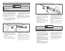
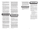
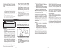
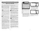
Locking the Trigger (Fig. 6)
Always lock trigger or remove battery pack
before changing accessories or performing
maintenance. Lock trigger when the tool is
not in use and when storing the tool.
1. To lock the trigger, push trigger lock in
the direction shown. The trigger will not
work when the trigger lock in the locked
position.
2. To unlock the trigger, push the trigger
lock in the direction shown.
WARNING!
When tool is not in use, lock trigger
to prevent the tool from being ac-
cidentally turned on.
Locked
Unlocked
Adjusting Plunger Rod
1. To manually adjust plunger rod, press in
and hold rod release trigger.
2. Grasp plunger rod handle and either
push or pull rod in or out.
3. Release rod release trigger.
NOTE: Keep plunger rod clean of material.
Retracting a plunger that is covered with
material may damage the internal parts of
the tool.
Electronic Overload Protection
The gun is protected by an electronic over-
load protection feature. If too much pressure
is exerted on the tube, the motor will auto-
matically reverse for one second, and then
shut down. This helps to prevent damage to
the tool and the caulk tube or pack.
If the motor shuts off, make sure that:
• Nozzle tip is cut
• Inner seal in the caulk tube is broken
• Hardened material is removed from the
nozzle
• Caulk tube is not damaged or frozen
• Plunger rod is free of caulk/adhesive
materials
Release trigger to allow the electronics to
reset. If the motor continues to shut off, try
another tube of material or take the tool to a
MILWAUKEE Service Center.
Auto-Reverse Mechanism
The auto-reverse feature reverses the plung-
er when the trigger is pressed for more than 1
second and then released. This helps to stop
excess material from continuing to fl ow.
Pulsing the trigger will deactivate the auto-
reverse mechanism and allow for continued
pressure on the tube. This helps maintain a
slower material feed rate.
Fig. 6