


page 6
OPERATION
To reduce the risk of injury, wear safety goggles or glasses
with side shields.
WARNING!
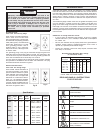
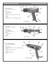
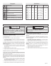
Using the Temperature Control Switch (Fig. 1-4)
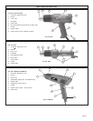
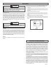
Cat. No. 8975 (Fig. 1)
Dual temperature control heat guns are provided with a 3 position rocker
switch. Place the switch in the center position for Low range or press
in the lower position of the switch completely for High range. The
markings on the switch correspond to these positions:
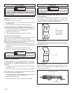
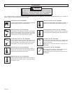
Cat. No. 8977 (Fig. 2)
Variable temperature model heat guns are marked O for OFF and l for
ON. Temperature is controlled by turning the end cap in the directions
dictated by the arrows.
Fig. 1
Fig. 2
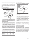
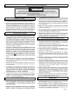
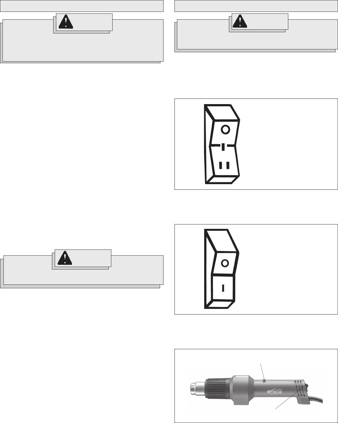
Cat. No. 8978 (Fig. 3)
Electronic temperature control system heat guns allow the tool to pro-
duce a greater concentration of heat at the nozzle, allowing the use of
various accessory nozzles.
Fig. 3
Heat adjustment knob
On / off switch
TOOL ASSEMBLY
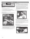
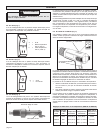
Installing Reduction Nozzles
Reduction nozzles are used to intensify the application of heat in a
specific area.
For reduction nozzle Cat. No. 49-80-0297:
1. To install the reduction nozzle to the heat gun, slide the nozzle onto
the heat gun nose.
2. Adjust heat, distance and length of application as necessary.
For reduction nozzles Cat. No. 49-80-0305, 49-80-0306 (For use with
electronic controlled heat guns 8978, 8986-20 and 8988-20 only):
1. To install the reduction nozzle to the heat gun, align the grooves on
the nozzle with the grooves on the heat gun nose.
2. Slide the nozzle onto the nose.
3. Adjust heat, distance and length of application as necessary.
Installing Slit and Cutting Nozzles
The slit nozzle Cat. No. 49-80-0308 is used for lap welding. The cutting
nozzle Cat. No. 49-80-0309 is used as a heated cutting edge.
NOTE: The reduction nozzle Cat. No. 49-80-0305 is needed as an at-
tachment for the slit and cutting nozzles. (For use with electronic con-
trolled heat guns 8978, 8986-20 and 8988-20 only):
1. To install the reduction nozzle to the heat gun, align the grooves on
the nozzle with the grooves on the heat gun nose and slide the nozzle
onto the nose.
2. Slide the slit or cutting nozzle onto the reduction nozzle.
3. Adjust heat, distance and length of application as necessary.
Installing Air Directing Nozzles
Air directing nozzles are used to change the direction of the airflow.
For hook nozzle Cat. No. 49-80-0292, deflector Cat. No. 49-80-0293,
air spreader Cat. No. 49-80-0294, soldering reflector nozzle Cat. No.
49-80-0307:
1. To install an air directing nozzle to the heat gun, slide the nozzle onto
the heat gun nose.
2. Adjust heat, distance and length of application as necessary.
For air reflector Cat. No. 49-80-0307 (For use with electronic controlled
heat guns 8978, 8986-20 and 8988-20 only):
1. To install the air reflector nozzle to the heat gun, align the grooves on
the nozzle with the grooves on the heat gun nose.
2. Slide the nozzle onto the nose.
3. Adjust heat, distance and length of application as necessary.
To reduce the risk of injury, always unplug tool before
attaching or removing accessories or making adjustments.
Use only specifically recommended accessories. Others
may be hazardous.
WARNING!
To reduce the risk of injury, do not remove accessory tips
until tool has cooled to room temperature.
WARNING!
O = Off
I = Low Temperature
570° F (300° C)
I I = High Temperature
1000° F (540° C)
O = Off
I = On