


page 7
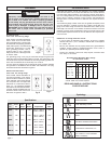
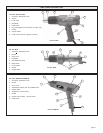
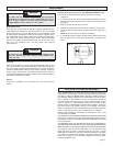
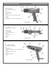
Cat. No. 8986-20 and 8988-20 (Fig. 4)
These heat guns have a variable temperature control switch, which
allows the user to adjust the temperature for specific applications.
The electronic control system regulates the temperature within the tools
heating element. Unlike non-electronic heat guns, MILWAUKEEs elec-
tronic heat gun will maintain the same temperature even when the air
flow is decreased or restricted with the use of accessory nozzles.
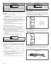
Cat. No. 8978 is a variable temperature heat gun with a range between
200° F and 1100° F (93° C to 593° C). The heat adjustment knob is a dial
with numbers 1 through 6 on it as shown. The lower numbers corre-
spond to cooler temperatures and higher numbers correspond to warmer
temperatures. To adjust temperature, simply turn the dial to the left or the
right.
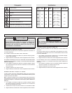
Airflow/Temperature Settings (8986-20 & 8988-20)
Airflow
Control
Switch
Setting
Position I
Position II
Position III
Airflow
Fan
Speed
High
Low
High
Minimum
Temperature
Setting
90°F
90°F
90°F
Maximum
Temperature
Setting
90°F
1100°F
1100°F
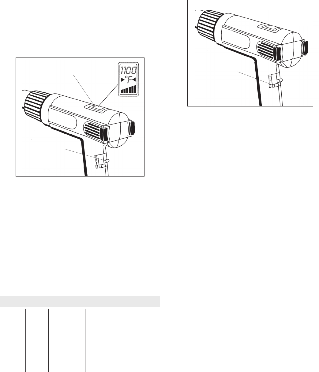
Fig. 4
Temperature
control switch
Temperature display
The electronic temperature control system regulates the temperature
within the tool's heating element. Unlike non-electronic heat guns,
MILWAUKEE's electronic heat gun will maintain the same temperature
even when the air flow is decreased or restricted with the use of
accessory nozzles. Refer to the airflow/temperature chart for various
airflow and temperature settings.
On Cat. No. 8988-20, a temperature display shows the heat gun
temperature setting.
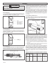
1. Slide the airflow control switch (blue switch) to Position II or III to
operate the temperature control switch.
2. To adjust the temperature, slide the temperature control switch (red
switch) to the desired position.
When the temperature control switch is set to the desired position on the
8988-20, the temperature for that position will show on the temperature
display. After 3 seconds, the temperature display will show the heat
guns actual temperature. The temperature display will continue to show
the actual temperature as the heat gun adjusts to the desired tempera-
ture set by the temperature control switch position.
Air Flow at
Maximum
Temperature
Setting
7 CFM*
8.8 CFM
16 CFM
* Cubic feet per minute
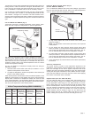
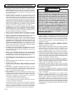
Using the Airflow Control Switch (Fig. 5)
(Cat. No. 8986-20 & 8988-20)
Cat. No. 8986-20 & 8988-20 have three airflow settings: high without
heat, low with heat and high with heat. Refer to the airflow/temperature
chart for various airflow and temperature settings.
1. For high airflow without heat, slide the airflow control switch (blue
switch) to Position I.
NOTE: The temperature control switch (red switch) will not operate
in this position.
2. For low airflow with heat, slide the airflow control switch (blue
switch) to Position II. The temperature may be adjusted from 90°F to
1100°F using the temperature control switch (red switch). The air-
flow will automatically increase as the temperature increases.
3. For high airflow with heat, slide the airflow control switch (blue
switch) to Position III. The temperature may be adjusted from 90°F to
1100°F using the temperature control switch (red switch). The air-
flow will automatically increase as the temperature increases.
4. To turn the heat gun off, slide the airflow control switch (blue switch)
to Position 0.
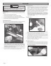
Selecting Temperature
The proper amount of heat for each application depends on the
temperature range selected, distance between the nozzle and work-
piece, and the length of time heat is applied. Experiment with scrap
materials and start with lowest temperature range. Be cautious when
working until the proper combination of heat, distance and time of appli-
cation has been obtained. Use a back and forth motion when applying
heat unless concentrated heat is desirable.
Fig. 5
Airflow
control switch
Support Stand (Cat. Nos. 8975 and 8977)
Cat. Nos. 8975 and 8977 have a support stand, which allows you to
position the heat gun upright on a workbench, leaving both hands free
for your application. When using Cat. Nos. 8975 and 8977 on a work-
bench, always place tool on a flat surface and snap the support stand
into the notched position. Place the cord so the heat gun wont tip. The
rear vent openings are designed to allow air flow even when the tool is
resting on the end cap, but it is important not to cover the vents with
foreign materials such as clothing or rags. Cat. No. 8978 has a flat
bottom surface that acts as a support stand. Rest the tool on the flat
surface, making sure to place the cord so the heat gun wont tip.