


page 5
OPERATION
WARNING!
To reduce the risk of injury, wear safety goggles or glasses
with side shields. Unplug the tool before changing accesso-
ries or making adjustments.
Starting and Stopping the Motor
Plug in the tool. To start the tool, squeeze the paddle trigger. Release the
paddle trigger to stop tool.
1. To start the tool, squeeze the paddle trigger.
2. To stop the tool, release the paddle trigger.
Sanding Disc and Grinding Wheel Selection
Use sanding discs and grinding wheels that are:
correct size as written on tool's nameplate.
correct wheel type and grit for the job.
rated at or above the RPM listed in the "WARNING" section on
the tool's nameplate.
Use backing pads, adapters, and other accessories that are:
correct size for tool and for sanding disc or grinding wheel.
rated at or above the RPM listed in the "WARNING" section on
the tool's nameplate.
the proper accessory for the job.
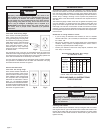
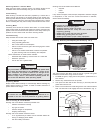
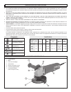
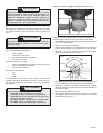
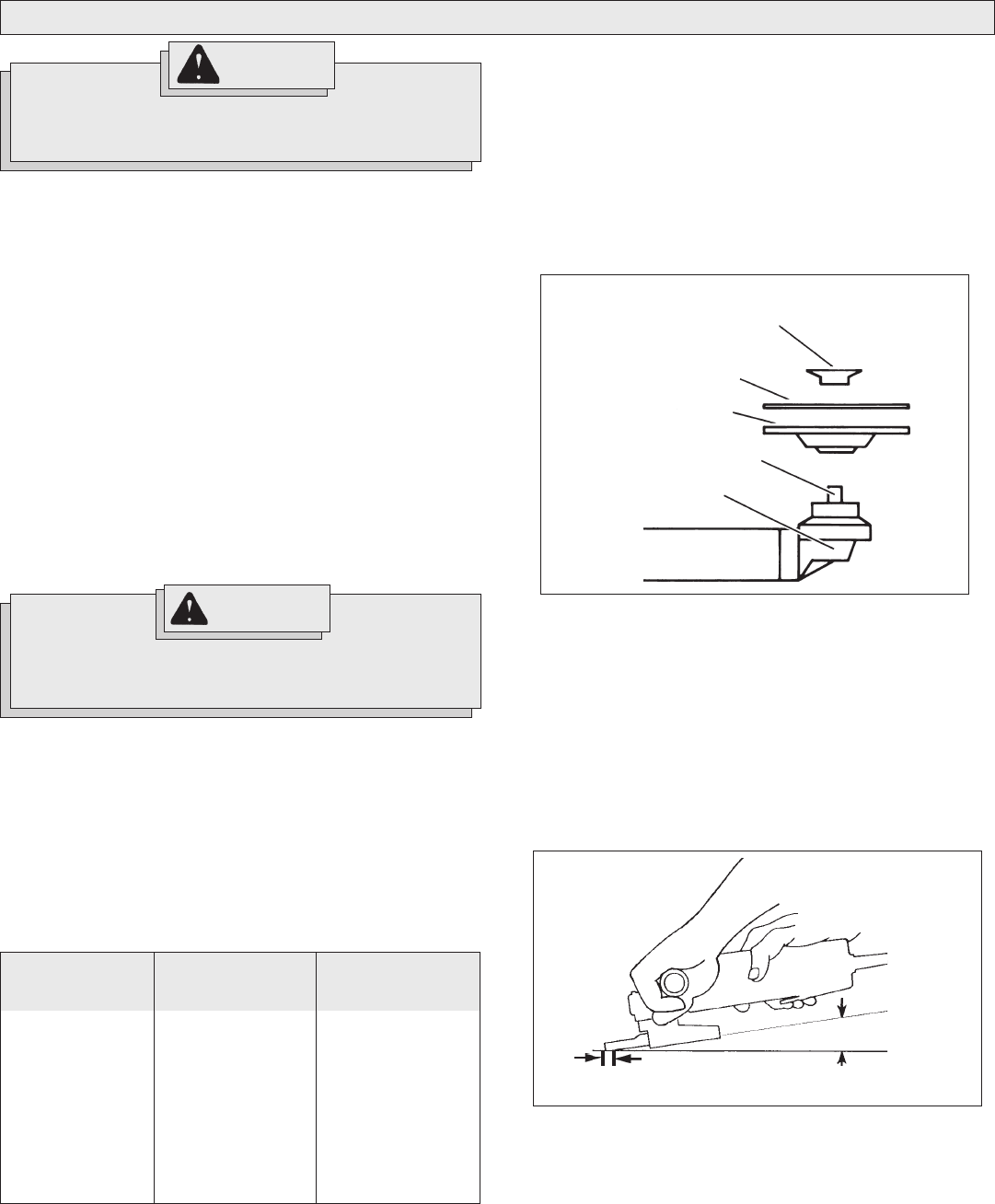
Installing Backing Pad and Sanding Discs (Fig. 1)
1. Unplug tool and place it upside down on a level surface as shown.
Remove any accessories from spindle.
2. Slip backing pad onto spindle with flat side away from gear case.
Place sanding disc on backing pad and secure assembly to spindle
with disc nut.
3. To tighten, press the spindle lock button while turning disc nut clock-
wise.
4. To remove backing pad and sanding disc, unplug tool and reverse
procedure.
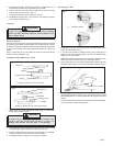
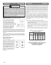
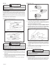
Sanding (Fig. 2)
1. Use a clamp, vise or other practical means to hold your work, free-
ing both hands to control your tool. Firmly grasp body of tool and
side handle before starting and while tool is in operation. Allow
sanding disc to come to full speed before beginning to sand.
2. Hold Sander/Grinder at 5° to 15° angle as shown to ensure proper
sanding pressure and control. Too great an angle will result in too
much pressure and could cause excessive wear to the disc and
workpiece. Too small an angle will reduce control.
3. Use long, sweeping, side to side strokes, advancing forward to
produce the desired finish.
Fig. 1
Gear Case
Spindle
Backing Pad
Disc Nut
Sanding Disc
Fig. 2
For best result use only this portion of disc
Hold at a 5° to 15° angle
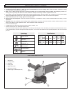
Ceramic
Lasts up to 3 times
longer than aluminum
oxide discs. For
general metal work-
ing. Ideal for tough
jobs.
Aluminum
Zirconia Bi-Cut
Unique grit pattern is
arranged in clusters
for faster stock re-
moval and cleaning.
Ideal for removing
paint from cars,
boats, etc. without
clogging.
Aluminum
Oxide
For fast cutting, gen-
eral purpose discs
for most metal jobs.
Best for cold-rolled
steel, stainless steel
or metals requiring
tough, fast cutting,
long lasting abra-
sives.
Sanding Disc and Grinding Wheel Material
Sanding discs and grinding wheels are made of various materials and
are designed for different jobs. Be sure that you choose the proper
sanding disc or grinding wheel for the job you plan to do.
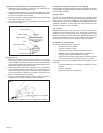
Selecting Sanding Discs & Grit
Refer to the table below to select the correct type of sanding disc for
your job. Generally, use 24 or 36 grit for heavy stock removal; 50, 60, or
80 grit for medium stock removal and 120 grit for finishing. Always begin
with a coarse grit, using successively finer grits to obtain the desired
finish. See Catalogor a complete list of MILWAUKEE sanding discs.
To reduce the risk of personal injury and damage to the tool,
use ONLY accessories rated at or above the RPM listed on the
WARNING section of the tool's nameplate.
WARNING!